 Entrance
Vibration motor in the thunderstorm recorder. DIY thunderstorm recorder
benefit this device tourists, hikers, fishermen, hunters, etc. will certainly appreciate it. Register a thunderstorm by means of it it is possible at a distance of approximately 80 km. In most cases, this is enough to take cover, hide, and de-energize electrical equipment in time.
Since the design of the registrar does not contain rare and expensive parts, almost everyone can assemble it. The only thing you will have to do is to tinker with the sensitivity threshold of the detector (adjust R4).
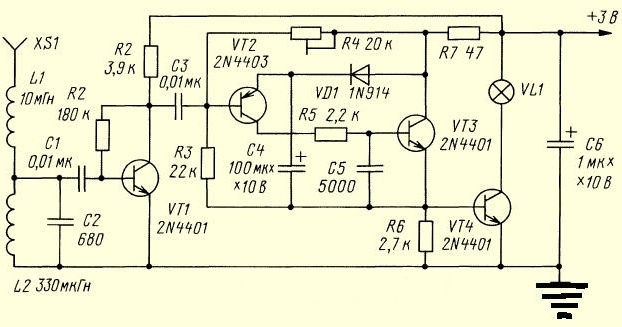
Device diagram:

The extension coil L1 improves the overall efficiency of the device. The tuning frequency of the input circuit L2 C2 is approximately 330 kHz.
Any circuit is taken from an old radio. L2 - wound with 0.2 mm wire. 360 turns per frame with a diameter of 5 mm. The winding height is 1 cm. The parameters for the L1 circuit are similar, only the turns are not 360, but 58. You can experiment with the second coil, remove it completely or replace it with another one.
The following parts are used in the thunderstorm recorder:
- transistors VT 1 - 4 (any from KT 315-361 to KT 3102-3107 will do;
- any pulse diode VD1.
Principle of operation: cascade recorder (VT2-VT4) receives a signal amplified by transistor VT1. Transistors VT2 and VT3 open with an RF pulse, then the capacitor C4 is discharged. Diode VD1 together with resistor R6, passing the charging current C4, initiate a longer opening of the transistor VT4 and activation of the VL1 indicator lamp.
Printed circuit board LAY format.

It is allowed to use not only an LED, but also an audible indicator with an integrated generator, as it suits you. To check the registrar, you can use a piezo lighter. The device should work on clicking a lighter from a distance of half a meter. It is recommended to ground the thunderstorm recorder, this will increase the sensitivity.
Photo rights belong to Alexey Shepelev
This simple design allows you to track changes in atmospheric charge. For example, by fixing an increase in atmospheric discharge, one can predict the approach of a thunderstorm front. The magnitude of the atmospheric charge on a sunny day is about 100 mV, but with the accumulation of thunderclouds and before rain, the magnitude electric charge increases many times over.
In the event of a thunderstorm, the voltage can increase to several thousand volts shortly before a lightning strike. This describes the circuit of the atmospheric electricity monitor, the change of which is displayed on the LED bar.
Description of the operation of the atmospheric electricity detector
The input circuit consists of an antenna, the signal from which is fed to the operational amplifier DA1 (TL071) used as a comparator. This type of op-amp has a JFET input and gain up to 100 dB. Its non-inverting input is connected to a voltage divider formed from resistors R3 and R4, and the non-inverting input is connected to an antenna.
Resistor R2 protects DA1 from excessively dangerous input voltage, while resistor R1 keeps the non-inverting input stable. Since the TL071 operational amplifier has a very high gain, a resistor R5 is added to the circuit, forming feedback with appropriate restrictions.
Depending on the input voltage, output 6 of DA1 will have a voltage in the range from 2.5 to 5 V, which is fed to input 5 of the LM3914 (DD1) chip through variable resistor R6. Resistor R7 limits the maximum sensitivity.
An IC is an integrated circuit that is capable of measuring (linear) input voltage and outputting the values to a string of LEDs. In fact, it turns out a classic analog LED display. The current flowing through the LEDs is limited by the LM3914 itself, so there is no need to external resistors. In this circuit, the input voltage from 1.7 to 4.2 V is distributed to five LEDs.
Device setup
Before switching on for the first time, turn the knob of the variable resistor R3 fully counterclockwise, and the variable resistor R6 to about the middle of the range. Apply power and turn the slider of the resistor R6 to test the device. Usually the VD2 LED lights up and even for a short time VD1, this indicates the correct operation of the equipment and changes in the atmospheric charge.
The final settings should be made on a sunny day with a clear sky, it is necessary to rotate R4 to achieve the glow of only VD5, which indicates normal atmospheric electricity. The scheme, despite its simplicity, works very well and allows you to warn of the approach of a thunderstorm long before it starts.
An insulated wire about 3 meters long can be used as an antenna, and the common wire of the circuit can be grounded, for example, connected to a central heating battery.
Attention! To avoid being struck by lightning during a thunderstorm, you must disconnect the antenna from the device.
DIY thunderstorm recorder
This device is perfect for those who are engaged in tourism, hiking, and not only. It allows register a thunderstorm within a radius of about 80 km, which will allow you to find shelter in time, hide, turn off electrical equipment.
Assembling a thunderstorm recorder is not so difficult, since it does not contain scarce parts and special settings, you just need to adjust R4 - this is the detector's sensitivity threshold.

Extension coil L1 boosts its effectiveness. The input circuit L2 C2 is tuned to a frequency of about 330 kHz.
L2-dangle on any circuit from an old radio, frame diameter 5mm, 360 turns of wire 0.2mm, winding height 10mm. The L1 circuit has the same parameters, only 58 turns of 0.2mm wire, in my version of this coil there is no, I replaced it with another one - you can experiment with it.
Printed circuit board in LAY format.

On the details of a homemade thunderstorm approach recorder. Transistors VT1-VT4 can be any, from KT315 / KT361 to KT3102 / KT3107. Diode VD1 - any pulse.
Operating principle: the signal amplified by the transistor VT1 is fed to the recording stage (VT2-VT4). The RF pulse opens transistors VT2 and VT3 and discharges capacitor C4. Its charging current, passing through the VD1 diode and the R6 resistor, leads to a longer opening of the VT4 transistor and the ignition of the VL1 indicator light.
You can use an LED or a sound indicator with a built-in generator - whichever is more convenient for you. You can check the registrar with a piezo lighter - by clicking the lighter at a distance of half a meter from the antenna. It is recommended to ground the device, so there will be more sensitivity.
This device is perfect for those who are engaged in tourism, hiking, and not only. It allows you to register a thunderstorm within a radius of about 80 km, which will allow you to find shelter in time, hide, turn off electrical equipment. Assembling a thunderstorm recorder is not so difficult, since it does not contain scarce parts and special settings, you just need to adjust R4 - this is the detector's sensitivity threshold.
Scheme:

The extension coil L1 increases its efficiency. The input circuit L2 C2 is tuned to a frequency of about 330 kHz. L2-winds on any circuit from an old radio, frame diameter 5mm, 360 turns of wire 0.2mm, winding height 10mm. The L1 circuit has the same parameters, only 58 turns of 0.2mm wire, in my version of this coil there is no, I replaced it with another one - you can experiment with it.

On the details of a homemade thunderstorm approach recorder. Transistors VT1-VT4 can be any, from KT315 / KT361 to KT3102 / KT3107. Diode VD1 - any pulse.
Operating principle: the signal amplified by the transistor VT1 is fed to the recording stage (VT2-VT4). The RF pulse opens transistors VT2 and VT3 and discharges capacitor C4. Its charging current, passing through the VD1 diode and the R6 resistor, leads to a longer opening of the VT4 transistor and the ignition of the VL1 indicator light. You can use an LED or a sound indicator with a built-in generator - whichever is more convenient for you. You can check the registrar with a piezo lighter - by clicking the lighter at a distance of half a meter from the antenna. It is recommended to ground the device, so there will be more sensitivity.
Download printed circuit board in LAY format:
You do not have access to download files from our server
This device is perfect for those who are engaged in tourism, hiking, and not only. It allows detect a thunderstorm within a radius of about 80 km, which will allow you to find shelter in time, hide, turn off electrical equipment.
Assembling a thunderstorm recorder is not so difficult, since it does not contain scarce parts and special settings, you just need to adjust R4 - this is the detector's sensitivity threshold.
Extension coil L1 boosts its effectiveness. The input circuit L2 C2 is tuned to a frequency of about 330 kHz.
L2-dangle on any circuit from an old radio, frame diameter 5mm, 360 turns of wire 0.2mm, winding height 10mm. The L1 circuit has the same parameters, only 58 turns of 0.2mm wire, in my version of this coil there is no, I replaced it with another one - you can experiment with it.

On the details of a homemade thunderstorm approach recorder. Transistors VT1-VT4 can be any, from KT315 / KT361 to KT3102 / KT3107. Diode VD1 - any pulse.
Operating principle: selected in the oscillatory circuit and amplified by the transistor VT1, the signal enters the recording stage (VT2-VT4). The RF pulse opens transistors VT2 and VT3 and discharges capacitor C4. Its charging current, passing through the VD1 diode and the R6 resistor, leads to a longer opening of the VT4 transistor and the ignition of the VL1 indicator light.
You can use an LED or a sound indicator with a built-in generator - whichever is more convenient for you. You can check the registrar with a piezo lighter - by clicking the lighter at a distance of half a meter from the antenna. It is recommended to ground the device for greater sensitivity.