 entrance
A simple amplifier scheme on the transistor do it yourself. The highest quality sound amplifier electrical schemes unch
The amplifier is able to issue 2kW Pink powers, and 1.5kw continuously, which means that this amplifier is able to burn most of the speakers known to you. To present such power in action, you can connect (what I do not specifically do) are two successively connected 8 ohm dynamics into a 220V AC network. At the same time, on one speaker there will be 110V active voltage on the load of 8 Ohm - 1,500W. What do you think will work for a long time in such an acoustics mode. If still no desire to do this amplifier - go on ...
Amplifier description
First, let's look at the requirements for the achievement of 1.5kw for 4 Ohm. We need 77.5V current voltage, but we must have some stock, because the supply voltage will decrease under load, and there will always be some voltage drop on collector-emitter transitions and emitter resistors.
So the supply voltage should be ...
VDC \u003d VRMS * 1.414
VDC \u003d 77.5 * 1.414 \u003d ± 109.6V constant voltage
Since we did not take into account the losses, we must add about 3-5V for the end of the amplifier, and additionally 10V for a drop in supply voltage under full load.
Transformer at 2 x 90V will give voltage without load ± 130V (260V between extreme rectifier points), so that the power source you need to work with extreme caution
Bipolar transistors were selected as the most appropriate to perform an amplifier terminal cascade. This is primarily dictated by the supply voltage, which exceeds the boundary voltage for most MOSFET transistors. It is also a lot for bipolar transistors, but MJ15004 / 5, or MJ21193 / 4 comply with the requirements for maximum voltage, and it means that we will dwell.
P \u003d V? / R \u003d 65? / 4 \u003d 1056w
That is, equal to the average electrical heater ...
Remember that when working on an active load from 45 ° phase shifts, the dispersion power is almost doubled. Based on this, it follows that good cooling is vital for this amplifier, you will need good radiators, fans for compulsory cooling (natural convection will not help).
MJ15024 / 5 (or MJ21193 / 4) Transistors in the K-3 housing (iron with two conclusions as KT825 / 827), and are calculated on the dispersion of 250W at 25 ° C. The C-3 of the transistor is selected, because it has the highest rated dispersion power, because the thermal resistance is lower than any other transistor in the plastic case.
MJE340 / 350 In the stress amplifier cascade guarantees a good linearity. But even at a current through a 12mA cascade, power - 0.72w, so that Q4, Q6, Q9 and Q10 must have heat sinks. The transistor (Q5), which determines the offset of the terminal cascade, must be installed on the total radiator with the tip and have reliable thermal contact.
Short-circuit protection scheme (Q7, Q8) limits the current at 12a level and power allocated by one transistor about 175W, while the long-term operation of the amplifier is not allowed in this mode.
Professional amplifier 1500W scheme.
Additional feedback elements (R6A and C3A shown by dotted) are optional. They may be needed, in the event of self-excitation of the amplifier. Reverse diodes (D9 and D10) protect the amplifier transistors from the reverse EMF when working on an active load. 1N5404 series diodes can withstand peak currents up to 200A. Rated voltage should be at least 400V.
The VR1 100 OMO resistor is used to balancing the DC amplifier. With the ratings of the components specified in the diagram, the initial offset must be within ± 25mV, before setting. The VR2 resistor is used to set the terminal cascade resting current. Customize resting current measuring voltage on the R19 or R20 resistor that should be within 150mV.
The sensitivity of the input cascade is 1.77V for 900W per 8 ohms, or 1800W on 4 ohms.
Source of power:
The power supply required for the amplifier requires a serious approach in design. First you need a lower transformer with a capacity of at least 2kw,. Power filter capacitors should be calculated 150V and withstand up to 10A pulsating current. Capacitors not relevant to these requirements can simply explode when the amplifier is fulfilled.
An important detail is a bridge rectifier. Although the bridges on 35a seemingly can cope with the task, but the peak repetitive current exceeds the passport details of the bridges. I advise you to use two parallel bridges included as shown in the diagram. The rated voltage of the bridge rectifier must be minima 400V, and they must be installed on a sufficient heat sink to cool.
Power supply circuit for amplifier 1500W.
The diagram shows capacitors composed of four low-voltage as it is easier to find them, and the rectifier also consists of two parallel bridges.
Additional sources of voltage in 5V can be deleted at the same time, peak power will decrease from 2048W to 1920W that is irrelevant.
The P39 module is a soft start system and consists of a relay parallel to the contacts of which the resistors are included with the total power of 150W and the resulting resistance of 33 ohms.
There was a desire to collect a more powerful amplifier "A" class. After reading a sufficient number of relevant literature and chose from the most recent version of the most recent version. It was a 30-W amplifier appropriate in its parameters high-end amplifiers.
There were no changes to the trace of the original printed circuit boards, however, due to the lack of initial power transistors, a more reliable output stage was selected using 2SA1943 and 2SC5200 transistors. The use of these transistors in the end made it possible to provide a large output power of the amplifier. The schematic diagram of my version of the amplifier further.

This is an image of the boards assembled according to this scheme with TOSHIBA 2SA1943 and 2SC5200 transistors.

If you look closely, you can see on the printed circuit board together with all the components there are displacement resistors, they are 1 W carbon type power. It turned out that they are more thermostable. When working any high-power amplifier, a huge amount of heat is highlighted, therefore compliance with the constancy of the nominal electronic component when it is heated is an important condition for the quality of the device.

The collected version of the amplifier operates at a current of about 1.6 A and voltage of 35 V. With the result that 60 W power of the continuous power dissipates on the transistors in the output cascade. I must notice that this is only a third of the power they can withstand. Try to imagine how much heat is released on radiators when they are heated to 40 degrees.

The enhancer body is made with their own aluminum hands. Top plate and mounting stove 3 mm thick. The radiator consists of two parts, its overall dimensions are 420 x 180 x 35 mm. Fasteners - screws, mainly with a secret head of stainless steel and thread M5 or M3. The number of capacitors was increased to six, their total capacity of 220000 Igf. For nutrition, a toroidal transformer with a capacity of 500 W was used.

Power supply amplifier
A well-visible amplifier device that has copper tires of the corresponding design. A small toroid has been added, for the adjustable feed under the control of the DC protection circuit. There is also a HF filter in the power circuit. With all its simplicity, it is necessary to say deceptive simplicity, the topology of the board of this amplifier and the sound they are produced as if without any effort, implied in turn, the possibility of its infinite strengthening.
Oscillograms of work amplifier
Digging 3 dB at 208 kHz
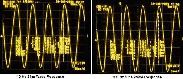
Sinusoid 10 Hz and 100 Hz

1 kHz sinusoid and 10 kHz
Signals 100 kHz and 1 MHz

Mandr 10 Hz and 100 Hz

Meander 1 kHz and 10 kHz

Full power 60 W clipping symmetry at 1 kHz frequency


Thus, it becomes clear that the simple and high-quality design of the UMP is not necessarily done using integrated circuits - only 8 transistors make it possible to achieve decent sound with the scheme, which can be collected for half a day.
He will have different dimensions and complexity of building a scheme. The article will immediately be affected by three types of amplifiers - on transistors, chips and lamps. And start worth it from the latter.
Lamp Unch
Such can often be found in the old equipment - televisions, radio receivers. Despite obsolescence, such a technique is still popular with Melomanov. There is an opinion that the lamp sound is much cleaner and more beautiful than "digitized". It is quite possible, in any case, such an effect, both from lamps, not achieve the use of transistor schemes. It is worth noting that the sound amplifier circuit (the simplest, using the lamps) can be implemented on only the triode.
In this case, the signal is necessary to feed the radiol mesh. The displacement voltage is supplied to the cathode - adjustable by selecting the resistance in the chain. The anode through the capacitor and the primary winding of the transformer is supplied to the supply voltage (over 150 volts). Accordingly, the secondary winding is connected to the dynamics. But this is a simple scheme, and in practice two- or three-stage structures are often used, in which there is a preliminary and terminal amplifier (on powerful lamps).
Disadvantages and advantages of lamp structures
What flaw can be the lamp technology? Above it was mentioned that anodic voltage should be over 150 volts. In addition to this, it is necessary to have an alternating voltage of 6.3 V to power the filaments of lamps. Sometimes 12.6 V is required, as there are lamps with such a voltage of the heat. Hence the conclusion is a huge need to use massive transformers.

But there are advantages that distinguish a tube technique from transistor: ease of installation, durability, it is almost impossible to deal with the entire scheme. Unless to break the bulb cylinder to break it. What you can not say about the transistors - an overly heated sting of the soldering iron or static can easily destroy the structure of the transition. The same problem with chips.
Transistor schemes
The above is the sound amplifier scheme on transistors. As you can see, it is quite complicated - a large number of components are used that allow the entire system to work. But if you split them into small components, it turns out that not everything is difficult. And the whole scheme works almost the same as the above-described triode. In essence, the semiconductor transistor is nothing more than triode.

The simplest design is a scheme on one semiconductor, three voltages are applied to the base: from the plus power through the resistance is positive and the total wire is negative, as well as from the signal source. Removable signal from the collector. The above is an example of a sound amplifier diagram (simplest on transistors). It is not used in pure form.
Microcircuits
Much more modern and high quality will be an amplifier on chips. Before today, their great set. The simplest sound amplifier circuit on the chip contains an extremely small number of items. And to make an independently good UNG will be able to anyone who knows how to more or less to contact the soldering iron. As a rule, microcircuits contain a couple of capacitors and resistance.

All other elements needed for work are available in the crystal itself. But the most important thing is meal. For some designs, you need to use bipolar power supplies. Often the problem arises in them. Microcircuits that need such power, for example, it is quite difficult to use for the manufacture of a car amplifier.
Useful "Sticks"
Since the conversation began talking about amplifiers on chips, it will be useful to mention that they can be used with the payrolls. Specially for such devices microcircuits are produced. They contain all the necessary components, it will only remain correctly installing the entire device.
And you will have the opportunity to adjust the timbre of the sound of music. Along with the LED Equalizer, it will be not only convenient, but also a beautiful means of visualization of sound. And the most interesting for autoswool lovers is, of course, the possibility of connecting a subwoofer. But it is worth devoting a separate section, because the topic is interesting and informative.
Subwoofer is just
Advantages of modern amplifiers on chips
Having considered all the possible types of amplifiers, it can be concluded: the most high-quality and simple are manufactured only on a modern elementary base. A lot of microcircuits are available for low frequency amplifiers. As an example, you can cite the UNG type TDA with different digital designations.
They are used almost everywhere, as there are both low-power and powerful chips. For example, for portable computer columns, it is best to use chips that have no power above 2-3 W. But for automotive equipment or acoustics of the home theater, it is advisable to use microcircuits with a power of more than 30 W. But pay attention to what the sound is protected. Schemes should contain a fuse that will protect against short circuit in the chain.

Plus also in the fact that the massive power supply is not required, so you can use it without any problems, for example, from a laptop, PC, old MFP (new, as a rule, the power supply is inside). The ease of installation is what is important for novice radio amateurs. The only thing that is required for such devices is high-quality cooling. If we are talking about powerful technique, you will have to install forced - one or more coolers on the radiator.
The amplifier offered to your precious attention is easy to assemble, terribly simple in the setup (it does not actually require it), does not contain particularly deficient components and with all this has very old characteristics and easily pulls on the so-called Hi-Fi, so gently beloved by most citizens .The amplifier can work on the load of 4 and 8 ohms, can be used in the bridge inclusion on the load of 8 ohms, while it will give up 200 W.
Main characteristics:
Power supply, in .............................................. .................. ± 35
Current current in silence mode, ma ................................ 100
Input resistance, com ................................................ ........... 24.
Sensitivity (100 W, 8 Ohm), in ........................................ ...... 1,2
Output power (kg \u003d 0.04%), W ...................................... ........ 80.
Range of reproducible frequencies, Hz ............................. 10 - 30000
Signal / noise ratio (non-weighted), dB ............................. -73
The amplifier is completely on discrete elements, without any OU and other tricks. When working on the load 4 Ohm and nutrition 35 in the amplifier develops power up to 100 W. If there is a need to connect the load of 8 ohm power, you can increase to +/- 42 V, in this case, we get the same 100 W.It is very strong not recommended to increase the supply voltage of more than 42 V, otherwise you can remain without weekend transistors. When working in bridge mode, 8 ohm load should be used, otherwise, again, lose all the hopes for the survival of the output transistors. By the way, it is necessary to consider that protection against KZ in the load is not provided, so it is necessary to be careful.To use the amplifier in the bridge mode, you must fasten the MT input to the output of another amplifier, the signal is fed to the input. The remaining input closes on the overall wire. The R11 resistor serves to set the overcoming current of the output transistors. C4 condenser determines the upper border of the amplification and it is not necessary to reduce it - get self-excitation at high frequencies.
All resistors are 0.25 W with the exception of R18, R12, R13, R16, R17. The first three is 0.5 W, the last two - 5 W. The HL1 LED is not for beauty, so it is not necessary to push the surface of the supernoye diode and take it on the front panel. The diode should be the most common green color - it is important because the LEDs of other colors have another voltage drop.If suddenly someone was not lucky and he could not get the output transistors MJL4281 and MJL4302, they can be replaced by MJL21193 and MJL21194, respectively.Variable resistor R11 is best to take a multi-turn, although the usual one is suitable. There is nothing critical here - it is just more convenient to install rest current.
Analysis of letters of radio amateurs, allowed for the following conclusions. Firstly (and this is natural), everyone comes for the creation of common power amplifiers common in the circuitry (UMP); Secondly, the simpler the amplifier scheme, the less prepared radio amateurs are taken for its assembly; Thirdly, even experienced designers often ignore the well-known installation rules, which leads to failures when repetition of UMPs on a modern element database.
Based on the said, UMP was developed (see Fig. 1). Its main features - the use of OU in unconnecting mode, which expands the frequency band of signals reproducible without exceeding the rate of increasing the output voltage of the OU; The output cascade transistors - in the OE scheme, and the forefront - with a separated load in the circuits of emitters and collectors. The latter, in addition to the obvious constructive advantage, the possibility of placing all four transistors on the overall heat sink, gives certain advantages compared with the output cascade, in which the transistors are included according to the OK scheme.
The main technical characteristics of UMPs:
Nominal frequency range for non-uniformity ACH 2 dB: 20 \u200b\u200b- 20000 Hz
Rated output power on the load of 4 ohm resistance: 30 W
Maximum output power on 4 ohm resistance load: 42 W
Rated output power on the load of 8 ohm resistance: 15 W
Maximum output power on the load of 8 ohm resistance: 21 W
The harmonic coefficient at rated power in the nominal frequency range: not more than 0.01%
Nominal (maximum) Input voltage: 0.8 (1) in
Input resistance: 47 com
Output resistance: not more than 0.03 ohms
Relative noise level and background: -86 dB
The amplitude of the output voltage bursts when turning on and off the UMP: not more than 0.1 V
The DA1 OU feeds through the VT1 and VT2 transistors that reduce supply voltages to the required values. Transistor resting currents create voltage drops on R8 and R9 resistors, sufficient to provide the necessary bias voltage at the VT3, VT4 and VT5, VT6 transistors. At the same time, the bias voltage for the terminal cascade transistors is chosen by such (0.35 ... 0.4 V) so that they remain reliably closed when the supply voltage increases by 10 ... 15% and overheating by 60 ... 80 ° C. They are removed from the R12, R13 resistors, which simultaneously stabilize the mode of operation of the transistors of the forefront cascade and create local OCO for current.
The ratio between the resistances of the resistors R11 and R4 of the OOS circuit is selected from the condition of obtaining a nominal input voltage equal to 0.8 V. Turning the circuits of external correction and Balancing OU for simplicity in the diagram is not shown (this will be said in the section on the amplifier to establish an amplifier).
R3C2 R3C2 and FVCH C3R10 with cutoff frequencies in the 60 kHz region prevent the work of relatively low-frequency transistors VT3-VT6 at higher frequencies in order to avoid their breakdown. Capacitors C4, C5 adjust the FFH of the forefront and ended cascades, preventing their self-excitation with the unsuccessful installation.
The L1 coil increases the stability of the UMR with a significant capacitive load.
Umzch feeds from an unstabilized rectifier. It can be common to both channels of the stereoxylter, however, in this case, the capacitance of the C8 and C9 filter capacitor must be enlarged twice as well, and the diameter of the secondary winding of the T1 transformer is 1.5 times. Fuses include in the power chain of each of the amplifiers.
The worn design may be different, but some design features, on which the success of its repetition depends, must be taken into account.
Drawing of the printed circuit board and placement of details of one channel UMP
led in drawings:
The length of the details should be no more than 7 ... 10 mm (for easy installation, the conclusions of the DA1 conclusions are shortened to about 15 mm). In the umzch, it is necessary to use ceramic capacitors with a rated voltage of at least 50 V. fee can be fixed on the heat sink of the terminal cascade transistors using racks 15 ... 20 mm or in close proximity to it, applying any detachable connector to connect the terminal cascade For example, mRN-22 (connector sockets and pins are included in points 1-5). In the latter case, the resistance of the resistors R12 and R13 should be selected equal to 43 ... 47 Ohm, and on the connector socket with the transistors of VT5, VT6 connected to it, set resistors of the same resistance R12 'and R13' (this will prevent the failure of transistors when contacting the contact in the connector ). The length of the conductors between the board and the transistors of the terminal cascade should be no more than 100 mm.
In addition to the specified in the diagram, it is possible to apply the OU K140UD6B, K140UD7A, K5444A, however, the harmonic coefficient at frequencies above 5 kHz will increase in this case to about 0.3%.
The transistors of the forefront cascade are located on the heat sink bent from the plate with dimensions of 70x35x3 mm (excluding the paw with a hole with a diameter of 2.2 mm) from an aluminum alloy, which is fixed with a single screw with a nut with a nut to the board to prevent breaking of transistors with random mechanical effects.
The terminal cascade transistors can be arranged both in common for each channel of the heat sink, and on the heat sink, general for both channels. In the first case, they are fixed on the heat sink and isolate the latter from the UMR housing, in the second - isolate transistors, and the heat sink can be a structural element of the amplifier housing. To reduce heat resistance, the transistor housing - the heat sink must be used with a heat-conducting paste. When using individual (for each channel), the heat sinks can be used transistors in the plastic case, which, due to the small area of \u200b\u200bmetal bases, can overheat with a bad execution of gaskets or a loose thermal contact with the heat sink and an excessive amount of paste in the gap. In general, for both channels of the heat sink, it is advisable to install transistors in the metal case. The heat sink area per one transistor should be at least 500 cm2.
Montage of the urzch is of great importance, connecting its channels with a power source. Power wires (+22 V, -22 V and general) should be possibly shorter (to each channel they must be laid separately) and sufficiently large cross section (at maximum power of 42 W - at least 1.5 mm2). The wires of the same section should be connected to acoustic systems, as well as the chains of emitters and collectors of the terminal cascade transistors to the UMP board.
Finding the umzch with a disconnected terminal cascade. If a detachable connector is used to connect the parts of the UMPS, it is convenient to use a technological outlet to which only the power wires and the output of the ZCH signal generator are connected. When, directly connecting the terminal transistors with the UMPS card, it is sufficient to remove jumpers from solder from the circuit conductors of their bases and temporarily solder the last to the outputs of the emitters.
For the Balancing of the OU DA1 (if there is a need) on the board there are holes for trickening and permanent resistors or wire jumpers to connect the chip conclusions in accordance with the balancing scheme for a particular type. For example, for balancing OU K5444UD2 its conclusions 1 and 8 through the resistor resistance of 62 kΩ are connected to the removal of the engine and one of the conclusions of the resistive element of the trim resistor of 22 com. The oven withdrawal of this resistor is combined with a wire jumper with an OS output 7, and through the resistor resistance 75 com, with the output 5 (in Fig. 2, these elements are shown by dashed lines). When using the OU K544UD1, its conclusion 1 through the resistor resistance is 4.3 kΩ is connected to the leads of the trim resistor with the resistance of 1.5 com. Its free conclusion is connected to the output of 8 OU through a resistor resistance of 5.1 com, and to the output 7 - wire jumper. For balancing OU K140UD6 and K140UD7, resistors use the same denominations, but the free output of the adjustable resistor is connected through a constant resistor with an output 5, and with a jumper with an output of 4 oo. However, balancing may not be needed, so these parts are installed only if necessary.
The establishment is starting with the fact that the input of the amplifier is closed in short, the oscilloscope is connected to the output, included in the maximum sensitivity mode, and powered shortly. If there is no alternating voltage at the output, i.e. self-excitation is missing, the mode of operation of the transistors VT3, VT4 and the DA1 DA1 is measured. OU supply voltage should lie within + 13.5 ... 14 and -13,5 ... 14 V and be about the same (deviation is permissible in the range of 0.2 ... 0.3 V). The voltage drops on the resistors R12 and R13 should be equal to 0.35 ... 0.4 V. If they are significantly (more than 10%) differ from the specified value, it is necessary to select resistors R8, R9, following their new resistance remained the same. Replace resistors when the power is turned off. Approximate resistance of resistors for OU K5444UD2A is indicated in the diagram. When using OU K544UD1A and K140UD6 for the original one should select the resistance of 680 ohms, and when using K140ud7 - 560 ohms.
Visitors the resistors R8, R9, measure the constant voltage at the yget output and, if it exceeds 20 ... 30 mV, balance the DA1. Then connect the Bases of VT5 transistors VT5, VT6 to VT3, VT4 emitters, and, briefly turning on the power, is convinced that it is not self-excited in this form. The noise voltage and the vocabulary background with a closed input key should not exceed 1 mV.
Next to the exit, the urzch is connected by a resistor resistance of 16 ohms with a scattering power of 10 ... 15 W, open the input of the UMR, connect to it to a frequency of 1 kHz generator and, gradually increasing its signal before receiving the voltage load 13.5 ... 14 V, check symmetry Limitations of positive and negative semi-fell sinusoids.
The minimum (under the limits) of the constant voltage at the output of the amplifier is achieved if necessary, the final balance sheet DA1 is achieved. After that, it can be proceeded to measure the basic characteristics of the UMP, loading it with a nominal load - resistor with a resistance of 4 or 8 ohms.
It should, however, consider that an attempt to establish, and even more accurately assess the parameters of the UMP, assembled without complying with the above edge rules, without setting it to the place intended for it and not feeding it from its own power supply, not only will not give the desired result, But can lead to the failure of the output cascade transistors. To establish an umzch and measurement, its characteristics should be proceeding only after the complete completion of its design. Easy amplifier only apparent. It should not be forgotten that in the composition of both the DA1, and the umzch generally applied transistors with maximum generation frequencies of 100 ... 300 MHz, and at output cascades - with significant transition tanks that are able to lead to self-excitation even with the apparent absence of feedback chains and Loads of sufficient magnitude. A minor inductance of the wire of the Emitter chain, parallel location on a significant length of the wires of the base and collector chains can cause self-excitation at high frequencies, which is extremely dangerous for the transistors of the terminal and forefront cascades. (However, this is true not only for the device described, but also for the UMP, assembled on any other scheme.)
When measuring the harmonic coefficient and the relative level of noise and interference, it should be remembered for possible tips from the supply network, television and radio transmitters, televisions and other radio recovers due to poor shielding of connecting wires, the input of the UMP and sensitive measuring instruments, as well as in the absence of connecting them ungrounded enclosures with each other. Sometimes it is enough to rearrange in the outlet of the power cable for one of the instruments or the umzch to get an incorrect result. By the way, you should not be used by a known from the old radio amateur practice by the method of checking the umzch with a touch of the finger to its input chain. This can lead to this level of high-frequency tip, which the weekend transistors fail.
The considered scheme can be taken as a basis when creating an UMP with different output power. To do this, only you only need to change the range of the UMP and the power supply. Some recommendations on this may be learned from the table. When building an umzch with an output power of about 25 watts, part of the elements can be excluded (see Fig. 3). As can be seen, instead of a resistor in the circuit of the non-screwing input of the OU DA1, connected to the shared wire, a divider of R1-R3 resistors is applied here, which made it possible to abandon the average output of the secondary winding of the T1 network transformer. This allows the use of transformers with a secondary winding voltage 24 ... 28 V and ensures the protection of the acoustic system from failure when the terminal cascade is sample.
Ump according to the scheme in Fig. 3 can be installed on the same printed circuit board (see Fig. 2). In this case, the holes for the conclusions of the resistors R2, R5-R7 are left free, the resistors R8 and R9 are sold directly in the DA1 power supply chain, for which the wire jumpers are installed in the holes for the conclusions of the emitter and collectors of transistors VT1, VT2. At an output power of less than 25 W in the terminal cascade, the transistors of the KT805 and KT837 series with any letter indexes can be applied.
Note. Resistance resistors R8, R9 (UMP according to the scheme in Fig. 1) and R6, R7 (UMP according to the scheme in Fig. 3) are indicated approximately. Establishing the umzch according to the scheme of Fig. 3 does not differ from the above described above.