 entrance
Homemade tube preamplifiers review. Putting together a tube pre-amplifier
Today we have a useful homemade product for connoisseurs good sound: high quality tube amplifier DIY
Hello!
I decided to assemble a push-pull tube amplifier (my hands are itching very much) from the parts that I have accumulated over a long time: a case, lamps, sockets for them, transformers and so on.
I must say that I got all this good for nothing (you are free of charge) and the cost of my new project will be 0.00 hryvnia, and if I need to buy something in addition, I will buy it for rubles (since I started my project in Ukraine, but I will finish already in Russia).
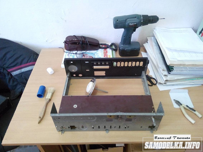
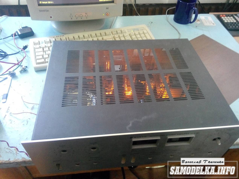
I'll start the description with the case.

Once upon a time it was, apparently, a good amplifier from SANYO, model DCA 411.
But I didn’t have a chance to listen to it, because I got it in a terrible dirty and inoperative state, it was dug up to impossible and a burnt 110 V networker (Japanese, probably) soaked all the insides. Instead of the native microcircuits of the final stage, there are some snot from Soviet transistors (this is a photo from the Internet of a good copy). In short, I gutted it all, and began to think. So, I didn’t think of anything better than putting a lamp tube in there (there’s quite a lot of space there).
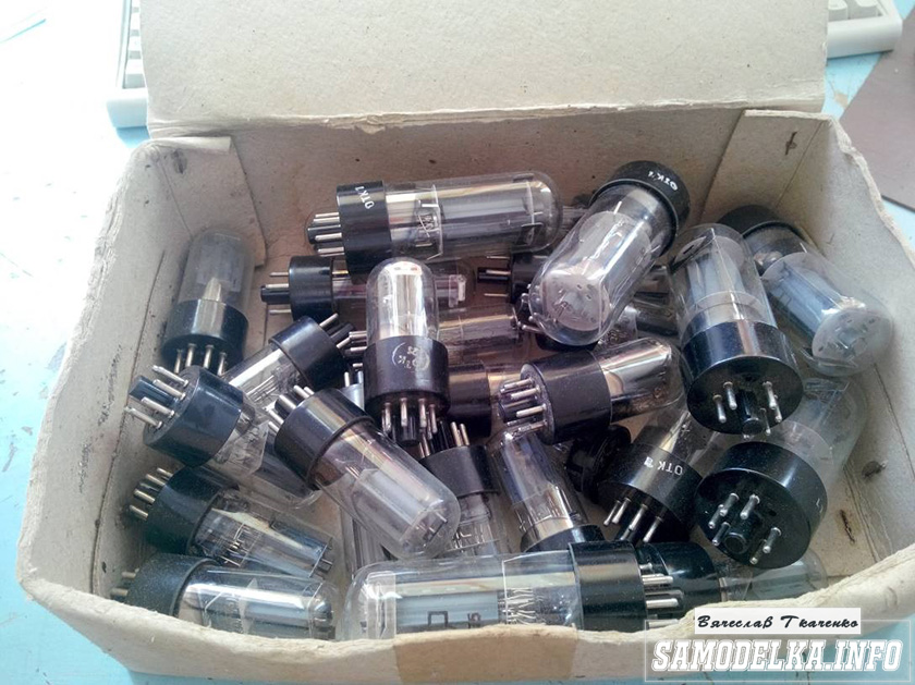
Decision is made. Now you need to decide on the diagram and details. I have a sufficient number of 6p3s and 6n9s lamps.


In view of the fact that I had already assembled a one-stroke amplifier for 6p3s, I wanted more power and, having rummaged in the vastness of the Internet, I chose this scheme of a push-pull amplifier for 6p3s.
Diagram of a homemade tube amplifier (ULF)
The scheme is taken from the site heavil.ru
I must say that the scheme is probably not the best one, but in view of its relative simplicity and the availability of parts, I decided to stop at it. Output transformer (an important figure in the plot).
It was decided to use the "legendary" TS-180 as output transformers. Don't throw stones right away (save them until the end of the article :)) I myself am in deep doubts about such a decision, but given my desire not to spend a dime on this project, I will continue.

I connected the trance conclusions for my case like this.
(8) - (7) (6) - (5) (2) - (1) (1 ′) - (2 ′) (5 ′) - (6 ′) (7 ′) - (8 ′) primary
(10) - (9) (9 ′) - (10 ′) secondary
anode voltage is applied to the connection of terminals 1 and 1 ', 8 and 8' to the anodes of the lamps.
10 and 10 'per speaker. (I didn’t come up with it myself, I found it on the Internet). To dispel the fog of pessimism, I decided to check frequency response transformer by eye. To do this, I assembled such a stand in haste.

In the photo, the GZ-102 generator, the BEAG APT-100 amplifier (100V-100W), the C1-65 oscilloscope, the 4 Ohm load equivalent (100W), and the transformer itself. By the way, the site is.
I put 1000 Hz with a swing of 80 (approximately) volts and fix the voltage on the oscilloscope screen (about 2 V). Then I increase the frequency and wait for the voltage on the secondary trance to begin to fall. I do the same in the direction of decreasing the frequency.
The result, I must say, pleased the frequency response is almost linear in the range from 30 Hz to 16 kHz, well, I thought it would be much worse. By the way, the BEAG APT-100 amplifier has a step-up transformer at the output and its frequency response, perhaps, is also not ideal.
Now you can collect everything to the heap in the body with a clear conscience. There is an idea to make the installation and layout inside in the best traditions of the so-called modding (minimum of wires in sight) and it would still be nice to make the backlighting with LEDs like in industrial copies.
Homemade tube amplifier power supply.
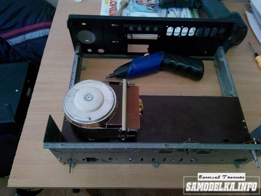
I will start the assembly with at the same time describe it. The heart of the power supply unit (and of the entire amplifier, probably) will be the TST-143 toroidal transformer, which I at one time (about 4 years ago) tore out with meat from some tube generator right while it was being taken to the landfill. Unfortunately, I didn’t have time for anything else. It’s a pity for such a generator, but maybe it was also a worker, or it could be repaired ... Okay, I’m distracted. Here he is my enforcer.


Of course, on the Internet I found a diagram for him.

The rectifier will be on a diode bridge with a filter on the choke for the anode supply. And 12 volts to power the backlight and anode voltage. I have such a choke.

Its inductance was 5 henry (according to the device), which is quite enough for good filtration. And the diode bridge was found like this.

Its name is BR1010. (10 amps 1000 volts). All I start to cut out the amplifier. I think it will be something like this.

I mark and cut out the holes in the PCB for the sockets for the light bulbs.
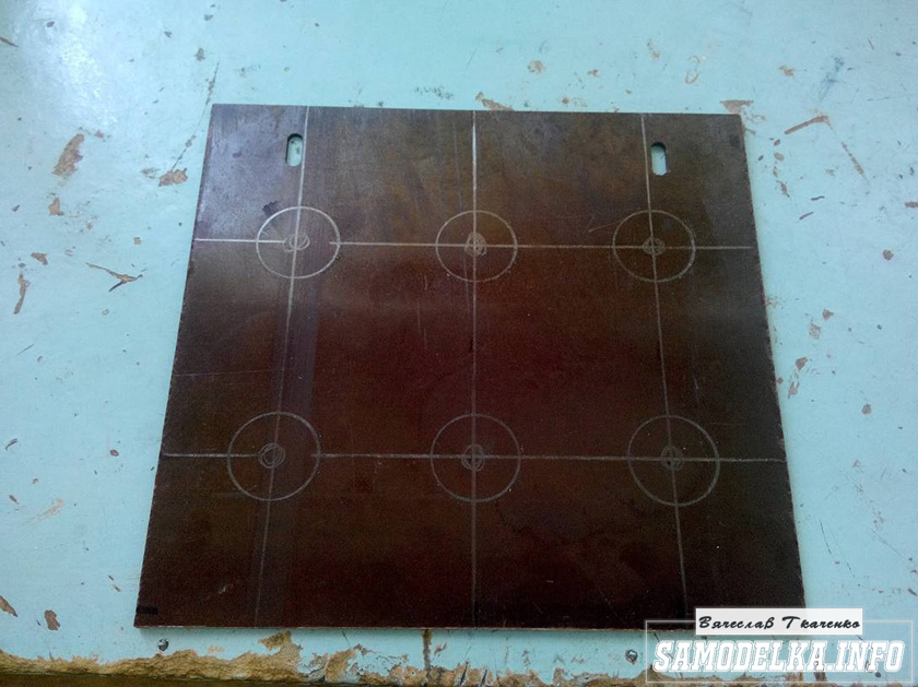
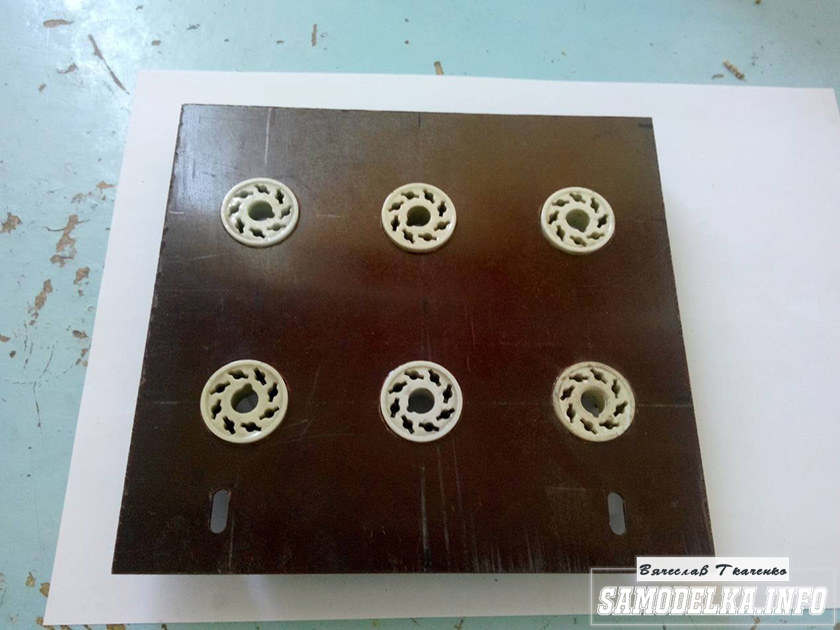


It turns out pretty good :) so far I like everything.

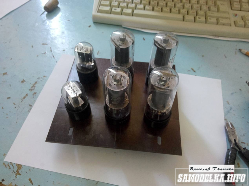
And so and so. drilling sawing :)
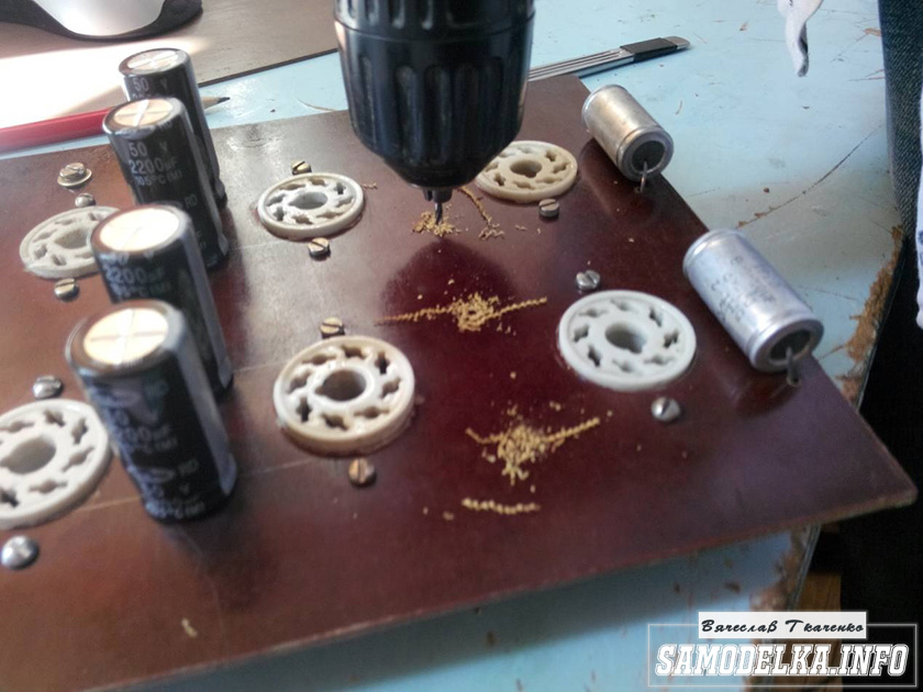
Something began to emerge.
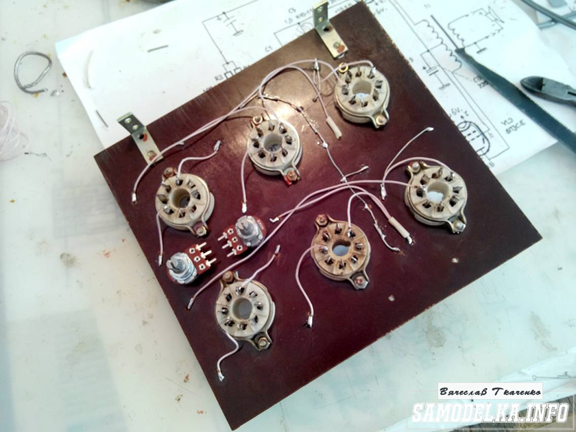
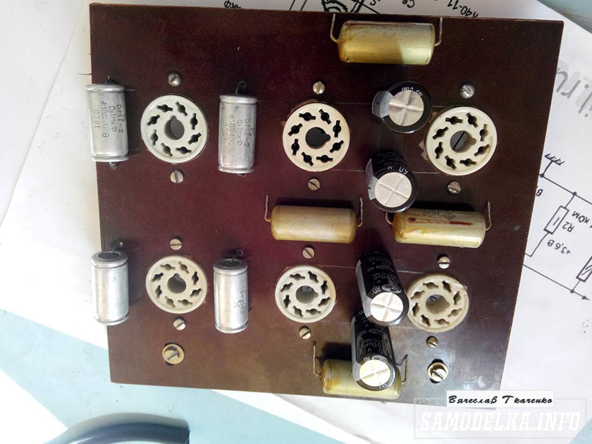
I found a fluoroplastic wire in the old stocks and immediately all the alternatives and compromises regarding the wire for installation disappeared without a trace :).


This is how the installation turned out. Everything seems to be "kosher", the incandescences are intertwined, the earth is in one, practically, point. Should work.

It's time to fence in food. After checking and dialing all the output trance windings, I soldered all the necessary wires to it, and began to install according to the adopted plan.

As you know, in ours it is not easy anywhere without improvised materials: this is how the container from the kinder surprise came in handy.

And a nescafe lid and an old CD


I pulled TVs and monitors out of the boards. All capacities are at least 400 volts (I know that I need more, but I don't want to buy).
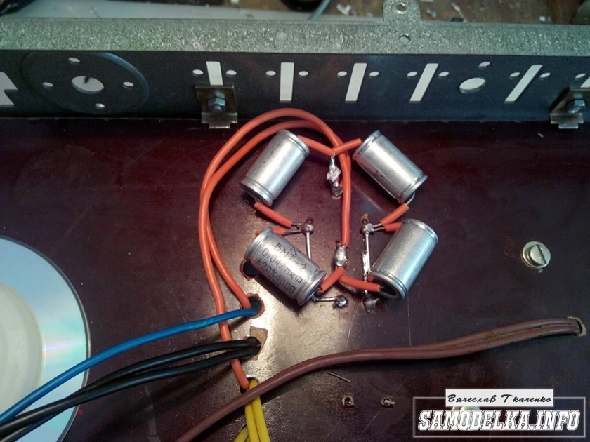
I shunt the bridge with containers (which were at hand, I will probably change later)

It turns out a bit too much, but oh well, it will sag under load :)

I use the power switch supplied by the amplifier (clear and soft).
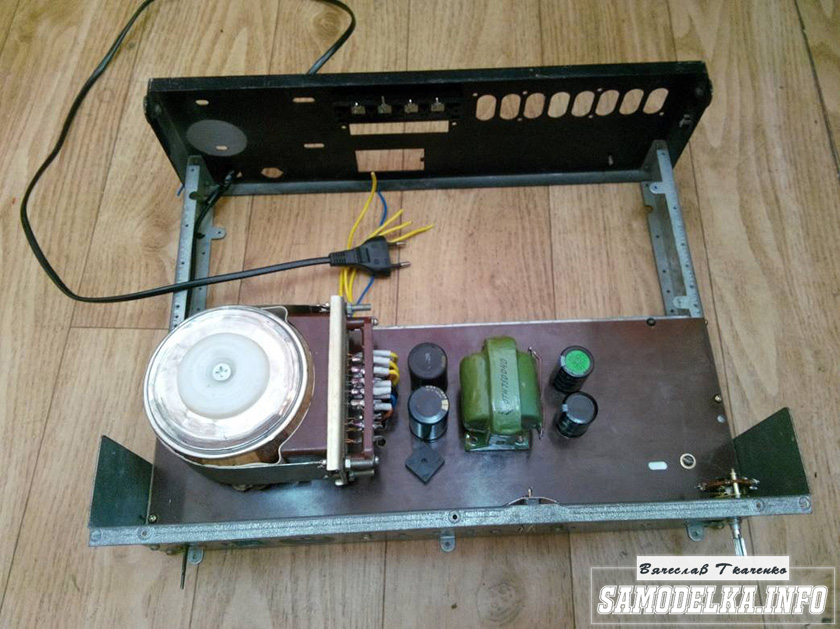
With that, you're done. It turned out well :)
Illumination for tube amplifier housing.
To implement the backlight, an LED strip was purchased.

And installed in the following way in the case.

The amplifier will now be visible in the daytime as well. To power the backlight, I will make a separate rectifier with a stabilizer on some KRKEN-like microcircuit (which I can find in the trash), from which I plan to power the anode voltage supply delay circuit.
Delay relay.
Having rummaged through the bins of my homeland, I found such a completely untouched thing.

This is a radio constructor for a time relay for a photomagnifier.


We collect, check, try on.


The response time was set to about 40 seconds, and the variable resistor was replaced with a constant one. The matter is coming to an end. It remains to put everything together, put the muzzle, indicators and regulators.
Regulators (variable at the entrance)
They say that the sound quality can strongly depend on them. In short, I put these
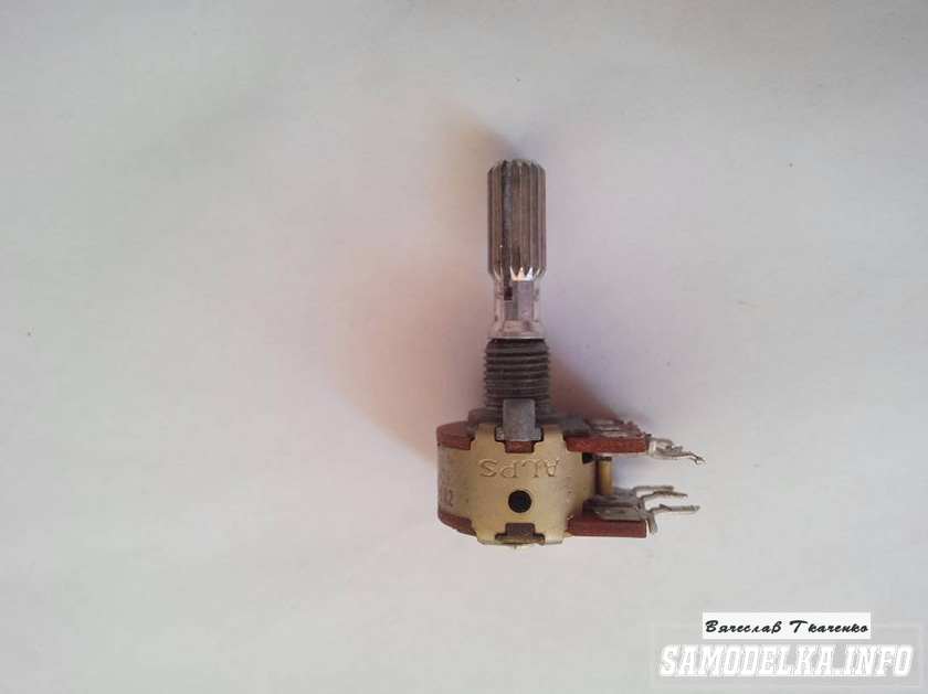
Twinned by 100 kOhm. since I have two of them, I decided to parallelize the outputs, thereby obtaining 50 kOhm and increased resistance to wheezing :)
Indicators.
I used the standard indicators, with standard backlight

The connection diagram was mercilessly bitten by me from the motherboard and was also involved.

Here's what I ended up with.


When checking the power, the amplifier showed a voltage at the output of 10 volts of an undistorted sine wave with a frequency of 1000 Hz for a load of 4 ohms (25 watts) equally across the channels, which made me happy :)
When listening to, the sound was crystal clear without background and dust, as they say, but too monitor, or what? nice but flat.
I naively thought that he would play without timbres, but ...
Using the software equalizer, we managed to get a very beautiful sound that everyone liked. Thank you all very much !!!
The author of the article "DIY self-made tube amplifier" Vyacheslav Tkachenko.
You may be interested in the following materials.
In the article, I tried to convey some experience of building a universal pre-amplifier using tubes.
Why on lamps?
Because this design initially assumed joint work as part of a tube audio complex, which, in addition to it, should include two tube monoblocks (single-cycle, 6E5P + GU-50).
The monoblocks are not yet ready, but during the test listening, an integral stereo amplifier of a similar composition was used, which together showed good results.
Ultimately, it all comes down to the speakers. The higher their quality, the less it is necessary to interfere with the sound path.
A well-tuned and properly made amplifier (not necessarily a tube amplifier), together with good acoustics, does not require the use of various kinds of "enhancers" and "optimizers" (IMHO). This is the ideal.
Well, what to do with our small-sized rooms, limited by financial means (for the majority, I think), when you still want not only to listen to your favorite music, but also to get a certain dose of adrenaline and feel the drive?
When my good friend, a wonderful athlete, music lover and life lover asked me to build him a preamplifier for a home stereo complex, the TOR (technical task, you know) sounded like this:
-that it is necessary to have a lamp;
- so that there is loudness, but in moderation;
- so that the bass and treble could be turned "to the fullest";
-to bring at least 4 signal sources to it;
-to adjust the volume separately by channel;
- so that you can "play" with the interconnect cable from the pre to the UMZCH;
- well, and so that the design is a "brick" (such, you know, a high-tech computer), well, hide the lamps, otherwise there is a lot of dust all around.
These are the initial parameters. Twist, Shura, twist!: dance:
After analyzing the situation, it was concluded that not all output stages of signal sources, even with low output impedance, are capable of operating on a rather complex complex load, which is a passive bridge tone control of Baxandal, especially those that have an initially low current rest, and possibly a low load capacity. In fairness, it must be said that the values of variable resistors were reduced to 100k (according to the original MAI scheme - 200 ... 220k), simply because they were available.
So, we need a buffer stage with good load capacity, low output impedance, quiescent current of at least 8-10 mA, with good impulse response and low harmonic distortion. We take the lamp the same as in the original circuit, 6N23P. Despite the large amount of controversy surrounding its use in audio equipment, I believe that its use is fully justified in many practical cases, including this specifically.
We do not save on lamps, given its cheapness and availability, we put a White follower at the input, one lamp at the input of each channel, at the output - a voltage amplifier - in total - three double triodes 6N23P, inexpensive and cheerful.
Why White Repeater? ,- you ask. I will explain this choice as follows:
- unlike a conventional cathode follower with a transfer ratio of about 0.7 ... 0.8, here we already have 0.96 and the ability to get a total transfer ratio of about 1.0 (attenuation in a passive RT compensates for the output stage of the UN);
- due to the presence of a positive feedback in White's follower, we have a lower output resistance compared to a simple cathode follower;
- with the "optimized" value of the positive feedback, we get a small harmonic distortion and "live" natural sound.
Again, we are not inventing anything new, everything has long been invented and optimized by famous audio gurus, such as John Bruski and his associates, who have repeated this construction many times.
It was decided to put this volume control on a resistor with one tap at the input after the switch. In fact, the load is also "not sugar", you need to check how it will behave after everything on the already tested signal sources. It turned out that it was pretty decent, so we finish the prototyping, draw the diagram -
Fragment is excluded. Our magazine exists on donations from readers. The full version of this article is available only
Fragment is excluded. Our magazine exists on donations from readers. The full version of this article is available only
In principle, I think that the circuit itself does not need any special comments. I want to note that White's repeater, implemented on a 6N23P lamp, is capable of operating on a very low-impedance load, well, for example, headphones with a resistance of 30 ohms or even less. And the passive tone block of Baksandal itself is calculated according to the program kindly provided by Evgeny Anatolyevich Moskatov. The program is very convenient and functional, easy to use and allows you to get a quick result in calculating the values of resistors and capacitors based on the potentiometers available to the radio amateur.
Finishing with the circuit of the preamplifier itself, I will mention that the classic UN at the output on the same 6N23P has a quiescent current of about 10 mA, an output impedance of about 2.5 kΩ and allows persistent experimenters and amateurs not only to twist different knobs, but also to adjust to the desired sound " the coveted "component of the audio path, having played around with various interconnect cables.
The power transformer TAN-1 127 / 220-50 was used. The anode voltage was obtained by the doubling circuit and has no characteristic features.
The filament voltage is stabilized, the reed switches and indication circuits of the switched on signal source, as well as the high voltage turn-on delay circuit (for about 40 seconds), assembled on an adjustable Zener diode SR1, transistor T2, relay RL1 (RES-48 passport RS 4.590. 204, 6 Volts, 42 ohms) and timing elements R5C9. For normal operation of the delay circuit, the capacitor C9 must be with a low leakage current, here it is composed of two tantalum electrolytes of Soviet production connected in parallel. Diode D13 - discharge, allows you to quickly restore the operation of the delay circuit after turning off the power.
The input selector switch can be used almost any, well, for example, a biscuit. It does not affect the passage sound signal, but only commutes the corresponding coils of reed switches and indication circuits of the switching on of the selected source. I had at hand some kind of 2-section imported biscuit maker, for 5 positions, tk. the number of inputs is four, the 5th pairs of contacts are not used. Indicator LEDs are selected in blue, with a diameter of 3 mm and fit well into the "interior". In their place, almost any LEDs can work, including incandescent bulbs - whoever likes what.
Instead of the commonly used method of supplying a "raising" potential to the incandescent circuit of lamps from a resistive voltage divider (to protect against breakdown of the filament-cathode and eliminate the background), a method often used abroad is used to connect the filament bus after the stabilizer to ground through a high-voltage capacitor C11.
The power transformer windings are wired appropriately to obtain the desired voltages and currents. In a standard TAN-1, two 6.3 volt filament windings are connected in parallel (which is a little small, but what can you do), a transistor (KT819) with a low collector-emitter saturation voltage and current gain is used to obtain the operating filament voltage (6.1 V) h21э is about 80. On the board, it is installed on a small heatsink, for which mounting holes are provided.
installed vertically on 2 x 10 mm racks -

from the back of the front panel:

Sami variable resistors have a design for printed wiring -


They are installed on one side of the printed circuit board, all other elements on the other.
Reed switch board:
Fragment is excluded. Our magazine exists on donations from readers. The full version of this article is available only
located on the rear wall, near the input RCA connectors, also on 2 x 10 mm stands used for mounting printed circuit boards.
The board is double-sided, on the one hand there are printed tracks, on the other there is a screen with holes countersunk under the legs.
The reed switches themselves - with two groups of contacts, of Chinese origin (how much without them),
as already mentioned type TRR-2A-05-D-00 in DIP package.
Low-power silicon self-induction damping diodes are soldered directly to the corresponding legs of the reed switches. Both boards are closed on top with a screen also made of foil-coated fiberglass. All of them are connected to the zero bus.
The power supply is also assembled on a printed circuit board
Fragment is excluded. Our magazine exists on donations from readers. The full version of this article is available only
installed vertically on the middle shelf with the help of an aluminum corner, under it a power transformer TAN-1 127 / 220-50 is mounted. A standard Euro power socket with a fuse inside is installed at the bottom of the rear wall. The lamps themselves are also placed on the middle shelf and all the corresponding "binding" is mounted by volumetric mounting on lamp panels and auxiliary mounting petals located next to them. The connections of the anode power supply and the incandescence of the lamps are made with twisted copper pairs of single-core wires of the 5th category with a diameter of 0.53 mm, which are laid computer networks... Their length should be minimal, according to the resulting construct. Shielded cable connecting the switch output to the volume control input - High Quality FURUTECH brands. The connection of the signal circuits RG and RT from printed circuit boards to the input lamps is made with shielded wires used for the installation of audio equipment from CLARION. Their length should also be as short as possible.
All the insides are visible in the photo:


I think no special comments are needed here. The neutral core is made of 1.5 mm copper wire and is connected to the body at one point on the back wall of the block. The power filter capacitors C3, C4, C13 and C14 are mounted directly on the petals of the mounting panels near the lamps.
All controls are brought out, at the very bottom there is a power switch, a little higher - a 4-position switch for controlling the switching of reed switches and an input selector indicator, 4 blue indicator LEDs, then separate volume controls and controls for bass and treble.
The design does not contain any super audiophile details, all resistors are MLT type, designed for the corresponding power, film capacitors, types K73-9, K73-11, K73-17, also for the corresponding voltages. Electrolytes made in Taiwan, similar to our K50-35 for a voltage of 400 V.
Almost any transistors in the power supply can be used, suitable for the parameters indicated in the diagram, their choice is not critical. Diodes in the anode power supply - any 600 V fast and a current of at least 1 A, and in a filament rectifier - you can use any diode assembly for a current of at least 3 A and a voltage of 50 V. A 0.5 mH choke - from an old German phone, you can put any other one or replace it with a resistor of one hundred ohms (1 watt).
The power transformer TAN-1 was also chosen because it ended up in the old storerooms. It is secured to the middle shelf via a rubber mat and operates quietly without hum.
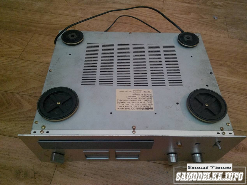
To eliminate unnecessary vibrations and microphonic effects, four rubber feet from an old phone are glued to the bottom of the unit using double-sided car tape of the 3M brand.
For homemade amateurs, skilful hands of craftsmen and professionals who have the necessary park of machines, here are the drawings of the body structure elements. Maybe someone will come in handy.
▼
🕗 28/01/11 ⚖️ 244.91 Kb ⇣ 212
Hello reader! My name is Igor, I'm 45, I'm a Siberian and an avid amateur electronics engineer. I have invented, created and maintain this wonderful site since 2006.
For more than 10 years, our magazine has existed solely at my expense.
Good! The freebie is over. If you want files and useful articles - help me!
In the wake of great interest in tube technology, I want to describe the design of a tube preamplifier "for the little ones." Or for not the smallest, but who do not have time for a serious deepening into the tube circuitry, but who want to try the "tube sound" and look at the pleasant warm glow of lamps in the dark. Definitely - the characteristics of this design are more than modest, but at the same time it is very functional and, most importantly, does not require special skills for assembly and does not contain expensive and rare elements.
The design is based on a common Soviet radio tube 6Zh1P- "high-frequency short-response pentode". Its detailed characteristics and application features are easy to find on the Internet, in particular, on the site that I myself use - The Magic of Lamps. His main feature, thanks to which we choose exactly it - the ability to work with low voltage. Yes, if you are interested in tube designs, you should certainly know that the anode voltage in most of them is hundreds of volts, which means you need an anode transformer, expensive high-voltage capacitors, an output (in fact, a step-down) transformer and, in the end, assembly precautions and skills. The second - no less important - is the unique cheapness and availability. All other parts are standard passive elements. You will have to order separately, perhaps only a linear stabilizer for 6V LM7806 (about it - separately), but - and even then - it can be replaced with an adjustable stabilizer LM317 or in general with a design with a transistor and a zener diode.
So, in order.
This device is considered a pre-amplifier very conditionally due to the rather low (unity) gain, which depends on the supply voltage. The main function of the device is matching the level and output impedance of the signal source with the load, and, of course, introducing into the signal a small level of specific distortions inherent in tube technology.
Source stereo signal for it can be a player, digital-to-analog converter (possibly as part of sound card) or electronic musical instrument (including those with high output impedance). The output from the device is fed directly to the power amplifier, or any device with a line input.
Scheme
It is really possible to assemble this device with all the parts at hand in one evening, taking into account the body work (even such as drilling large holes for lamp sockets). By the way, I strongly recommend taking a metal case. The electronics work will take hardly an hour.
Indeed, for one cascade ( there are two of them in the design - on the right and left channel) there is only a lamp (V1 / V2), a resistor in the anode circuit (R3 / R5) and a blocking capacitor at the output (C3 / C4). In addition, a potentiometer (R2 / R4) for adjusting the input signal level (I recommend a linear potentiometer with a resistance of approximately 50kOhm - 100kOhm), a blocking capacitor at the input - at will (I personally did not install it).
The rest of the circuit is the power circuit. C1, R1 and C2 - power filter and linear stabilizer DA1. It's worth dwelling on the DA1 chip. It is needed so that no more than the required 6.3V is supplied to the heating of the radio tubes. In this design, I used the closest in voltage LM7806 output 6V. As I wrote above, you can replace it with other solutions ( about them, if there is a need, I will tell you separately). It was also possible, of course, to make a separate heating power supply and a separate anode power supply. This would give us a few more options, but - at the same time - would greatly complicate the design... But with this inclusion, the entire circuit can be powered from a standard 12-18V adapter.
Now a few very important words about the power supply. As I wrote above, the gain of the circuit and dynamic range the higher the higher the supply voltage... However, there are limitations here. We will not take into account the maximum anode voltage of the lamps - it is quite high, we will focus on the weak link of the circuit - the stabilizer. The maximum voltage that can be applied to its input is 35V, maximum current - 1A. The filaments of two lamps together consume about 300mA... It would seem that the stock is pretty decent. However, in practice - the greater the current consumption and the input voltage - the more heat the stabilizer generates... See datasheets for exact thermal specifications and tolerances. Therefore, the maximum allowable supply voltage will be partly determined by the heat sink (radiator) on which the stabilizer will be installed.
In my design, for example, as a scattering surface is used metal case devices - the microcircuit is screwed to the wall through thermal paste. By the way, the insulating pad not required if you, as in most classic solutions, combine case with minus power supply(in our design, the power supply is unipolar and "minus" will be "mass" and, accordingly, shield the circuit). The case does not dissipate heat very well (not much, but it heats up noticeably in an hour of operation), so I limited the supply voltage to 12V. If you install the stabilizer on a sufficiently massive radiator ( just please don't overdo it! the basic idea of the design is compactness!!! ), then the voltage can be increased to 18-20V. Achieve limit value 35V I strongly advise against them, because they significantly reduce the service life of the element and soon it may fail from overheating!
The green numbers on the diagram next to the lamp leads are the electrode numbers. The location of the electrodes on a standard 7-pin panel is shown below.
Just in case, here is the purpose of the contacts for the linear stabilizer.
And, finally, the design itself.


Any metal case the size of a pack of cigarettes will do. In my case, it was once the D-Link Media Converter. Using a cone drill I made two large holes with a diameter of 22mm in the socket. It was decided to mount the installation hinged. For this design, a PCB is completely redundant. With so many radioelements, only two contact blocks of 10 contacts were enough, and they were not fully involved.
Don't forget about star connection of the earth- all taps going according to the scheme to "ground" must be connected at one point with power supply and housing. True, again, for such a simple circuit with a low anode voltage, this principle is not critical, although you should accustom yourself to observe it everywhere. Experienced electronics engineers will surely point out to me that the wires inside are not laid out the way they do in complex and expensive amplifiers. Of course, it is worth striving for this, but it is not for nothing that I wrote in the headline - "... in one evening." With such conditions, there is no time for perfectionism, but - on the other hand - I think this is a good demonstration that even the most novice radio amateur can cope with the assembly of the device.


That's all. A properly assembled structure works immediately. Personally, I am quite satisfied with the sound - at least it corresponds to the level. You can feed from an ordinary adapter, as mentioned above, with a voltage of 12-18V, but - preferably - stabilized. In this case, the likelihood of power pickups will be reduced. I listened through Soundtech Series A on Quested S6, the signal was sent from E-mu Tracker.
Good day!
Measurements are a long process, but processing of results and their registration takes even more time. But I still found the opportunity to prepare several graphs, at least for one separate scheme.
Attention: I am slower: I rarely write here, most often when I want to take time off from work)). And everything new and interesting, invariably fresh, immediately gets to Instagram. Click HERE, go to my account and subscribe :) I will always be very glad to you! Enjoy reading:)
Note: described tube voltage amplifier module
(his photo is at the very bottom)
, while lying idle and leisurely looking for a new owner). If suddenly you are interested in it - write to me in the comments, or in social networks (links to them at the end of the article). And then there are a couple of extra blank boards :)
Experimental circuit:

This is a tube stage with a common cathode and an anode current source. It compares favorably with the very common circuit with a resistor in the anode in the ability to change the lamp modes in much wider aisles, more precisely adjusting it to the task, and in the end to get results unattainable for a conventional lamp resistive stage.
The circuit contains a 6N1P lamp - a worthy and affordable representative of the lamp fraternity. If you believe the forums and reviews of some lamp lovers, its main drawback is the low price and availability for sale in a very large quantities... Due to the lack of elitism and uniqueness, it is often declared unfit for sound :).
However, on 6N1P the light did not converge like a wedge, and any other triode can be put into the circuit. 6N23P, 6N6P, 6N2P, 6N8S, etc ... everyone can choose a lamp to their liking). All you need to do is change resistor R3 and adjust the current source with resistor R6.
By the way, the 6N23P lamp works very well with the current source in the anode. Especially at low supply voltages. In any case, much better than at the same voltages, but with an anode resistor. For two months now I want to publish this data in a separate article, but something does not work out in any way :(.
Added on 08/22/2018: after all, after a long postponement, a record about 6N23P appeared. Diagrams, measurement results and comparisons on the link.
Let's go back to the 6N1P lamp:
Measurements were carried out for nine cases. Quiescent current ( Ia), took one of three values: 4.2 mA, 7.0 mA, 9.0 mA. For each of them, measurements were repeated with three load values Rн: 10 kOhm, 50 kOhm, 100 kOhm. For all combinations Ia and Rн the spectra of distortions were recorded at five different levels of the output signal ( Uout.amp.): 2.5 V, 5 V, 10 V, 20 V, 40 V (peak values).
The values Rн and Uout.amp. selected as are or may be found in our hybrid and pure tube amplifiers. The anode current is limited from above by the permissible lamp power. From the bottom, there is no limitation as such, but at values less than 4 mA, distortions in all measurements have a long spectrum, and therefore have no practical value for us and are contraindicated for use.
I put all the results in graphs, and they, in turn, collected in one big picture :). Rows are grouped by load resistance, columns by quiescent current. Distortion spectra for different levels of the output signal are drawn in different colors. Perhaps this design is overloaded and not very convenient for perception, but it better demonstrates the basic patterns.

Note: in a conventional stage (with a resistor in the anode), due to the fact that the quiescent current and the load resistance of the lamp are rigidly connected, the modes corresponding to the two bottom rows of the graphs are not available. We'll have to be content with modes close to the top three, or lower the anode current.
And here is a link to the results presented in the form of a table
A little bit about what can be seen here:
In general, I just wanted to show the results, and leave the conclusions outside the article. In the end, everyone can make them himself :). But after reflection, I nevertheless considered it necessary to outline some obvious patterns:
1. As expected, the distortion level drops as the load resistance rises. But the higher the anode current of the lamp (and with it its slope), the less noticeable is the effect of the load on distortion. Therefore, in hybrid amplifiers, in which a semiconductor circuit with a low input impedance is connected to the output of a tube preamplifier, it is necessary to increase the anode current of the lamp.
2. You can look at the situation from a different angle: the anode current strongly affects the level and spectrum of distortions, but the higher the load resistance, the less noticeable this influence is. Those. in pure tube circuits, where the load resistance can be very high, the plate current can be reduced without worrying too much about linearity issues.
3. It is clearly seen from the graphs that when working with output signal amplitudes up to 20 V, the 6N1P lamp in almost all modes has a beautiful spectrum with a low level and therefore is well suited for hybrid power amplifiers and excellent for earphones.
Few other numbers:
I was no less interested in the voltage gain, its dependence on the selected anode current and load resistance. For clarity, I again summarized the results in a graph:

Conclusion: the desired coefficient. gains can be easily adjusted by changing the resistance of the load resistor and the plate current. However, so that the linearity of the cascade does not suffer, it is worth checking the graphs of the distortion spectra when choosing the current and load.
It is also worth paying attention to the fact that with an increase in the quiescent current, the bias voltage of the lamp decreases (the voltage across the resistor R3). And along with them, the permissible input signal level. The bias voltages and their corresponding resistances of resistor R3 are plotted:

There are people who do not at all see the difference between film and digital photography, but there are people who do not hear the difference between digital and analog sound at all. It is very easy for such people to live, while others are constantly engaged in development and improvement, striving for perfection.
I want to note right away that if you do not hear the difference in the sound of two different audio systems (or for you it is not a reason to change something), feel free to scroll further and in no case go under cat. Simply because you will not understand anything anyway. And everyone else is welcome under the cat, where we will consider the simplest way degrade digital sound.
So let's go!
I will not retell the principles of work of radio tubes and explain why they are so widely used not only in expensive reproducing equipment, but first of all are actively used by musicians and in recording studios. Radio tubes are loved for the unique distortion they introduce into the sound path.
The simplest and affordable way correctly degrade the sound - use a tube PREAMPLIFIER. It boosts the signal level and adds unique distortion that cannot be obtained in any other way. The circuit of tube amplifiers is quite simple and can be easily found on the Internet. The most important thing when assembling such an amplifier yourself is accuracy and precision. You can do it easier and buy a ready-made two-channel tube amplifier from China. In general, the Chinese are great, this device costing less than 2,000 rubles is not at all a shame to connect even to a Hi-End class audio system.
One of mine acoustic systems of course simpler, but partly made by hand. The loudspeakers are assembled from components of automobile acoustics; the popular in the 90s is used as the main power amplifier transistor amplifier Pioneer A504r. And the sound source is the most ordinary iPhone connected using a Lightning-Jack adapter and a regular interconnect cable with RCA connectors. As you know, there is no limit to perfection, so the assembled equipment is gradually changing in pursuit of a worse sound.
The tube preamplifier comes with 6J1 tubes (pictured on the left), an analogue of the Soviet high-frequency 6Ж1 pentodes. The sound becomes worse with them, but not enough. This is especially noticeable when listening to rock and jazz compositions. For experiments, I bought several modifications of Soviet radio tubes on Avito: 6Zh3P, 6Zh5P and 6Zh38P. Each lamp costs from 100 to 250 rubles, depending on its condition. Usually these are lamps from the 70s and 80s, brand new and unused.
The greatest effect of sound deterioration was achieved with the help of high-frequency beam tetrodes - 6Zh5P. During operation, the lamps heat up to 65 degrees, and the sound is the most interesting with them. But this is only true for certain genres. For example, with electronic music, the complete 6J1 sound better (that is, worse) than Soviet radio tubes. In general, it is all a matter of personal taste and it cannot be argued that these lamps are better and others are worse.
To induce a butthott in those who stepped on a bear as a child, the Chinese added two small red LEDs at the base of the ports with radio tubes. This is a purely decorative lighting. not all types of lamps have their own visible glow during operation (for example, 6Zh5P do not glow at all, but they heat up more than others). But any sofa expert can say that the lamps in this amplifier are just for beauty :)
As a sound source - the fastest today and at that time the most inexpensive iPhone in the SE version, such a device now costs less than 20 thousand rubles. I'm lucky to have a phone from Hong Kong with sound. To diversify this sound a little, I purchased an ingenious sound degrader in the form of an adapter Lightning - Jack MMX62AM / A. Its price is only 600 rubles and I can confidently say that it is best opportunity change the sound of any audio system with a minimum investment. Considering that inside this adapter is a DAC, ADC and power amplifier, it's generally surprising why it is so cheap.
Chinese radio tubes 6J1 in operation.
Since we are talking about the entire audio system, interconnect cables can also be noted. Here everything is also quite simple and depends solely on personal preference. The evaluation criterion is very simple: like it or not. As an interconnect cable between the preamplifier and the final amplifier, I personally prefer a blue cable from an unknown manufacturer with simple Belsis connectors. But the Vention cable (pictured on the right), frankly, did not like it.
The picture is reversed between the sound source and the tube preamplifier. The Chinese brand Vention cable worth 350 rubles sounds at least no worse than the German Schulz Kabel worth 550 rubles. In general, you can even use aluminum hangers as wires, if you specifically like the sound (with noise, yyy). But if you really do not hear the difference between an interconnect unit for 50 rubles with an exorbitant level of interference and a normal acoustic cable, you can only envy that you have such an easy and simple life in your life.
But if you notice a difference in sound when replacing certain components (from wires to speakers), then I can safely recommend such a tube amplifier as the most affordable way to degrade the sound with the help of unique distortions inherent only in radio tubes. Well, or you can try to assemble a tube preamplifier with your own hands, if, of course, you have time for this.
I'll go and listen to this spoiled warm tube sound and have some tea.