 entrance
CHP OGS hydroacoustics Detection of goals. Hydroacoustic complexes pl in anti-submarine struggle
Soviet diesel-electric submarines of the post-war building Gagin Vladimir Vladimirovich
Hydroacoustic complexes pl in anti-submarine struggle
The diesel-electric boats of the first post-war projects "paved the road" for the crews of modern submarines, in the ocean campaigns, gaining operation of operation of military equipment, mastering the techniques of treated swimming, studying the hydrological and hydrographic situation of strategically important areas of the ocean, practicing the tactics of anti-palmary and anti-worr.
The tactics of anti-submarine struggle is often reduced to the search and detection of the Eagle PL using hydroacoustic means earlier than the enemy does.
At the same time, the state of the surrounding medium acquires the most important value, especially such parameters, as the zones of acoustic convergence and the position of the submarine relative to the "thermocline".
The convergence zones are ring-shaped areas around the underwater ship. The sound heading down from the convergence point located in the convergence zone is refracted depending on the pressure and temperature of the water, moves up and down with respect to the surface of the spiral through irregular intervals, which also depend on the state of the surrounding environment.
The commander of the ship, trying not to fall into these areas - as to where, in his opinion, the goal is, it can avoid detection. To do this, he needs to be within the areas where the sound applies to its source is simply radially.
The easiest way is to take a position above the layer of temperature jump (thermocline) or under it so that it shares the submarines - then the sounds published by its engine will most likely be reflected from the layer and the enemy boat will not detect it.
Temperature leap is a borderline layer of underwater space, separating warm superficial water and colder profound areas.
Diesel submarines Along with atomic, they occupy a prominent place in the aggressive plans of the NATO Block of the NATO countries. According to the reference book "Jane", in mid-1980, in the fleets of the North Atlantic Union, there were 186 diesel boats.
Diesel submarines have certain advantages of atomic, they are related, in particular, less noise, which improves the conditions for the operation of hydroacoustic stations (GAS) when solving the problems of anti-submarine struggle.
Currently, according to foreign press, the integration of hydroacoustic technology with Bius and weapon management systems occurring on the basis of a wide use of computers. As a result, the tactical capabilities of the hydroacoustic equipment changed qualitatively. The likelihood of detecting goals and classification of the received contact has increased. In addition, it became real at the same time to monitor several (up to six) targets and quickly detect changes in their maneuvering, automatically obtain information and continuously issue it into all conjugate systems and clearly, in a convenient application conveniently, to display on screens and screens, and If necessary, register.
Digital signal processing allowed the submarine passive location systems to determine only the noise of the bearer and the distance to it.
Finally, the integration of various systems based on computer simplified control over the work and maintenance of the GAS and allowed to reduce the service personnel, which is important for the relatively small water-disk of diesel submarines.
The main tract of the acoustic station is the noiselessness with a range of several tens of kilometers. In the low-frequency (220 Hz - 7 kHz) the signal reception range occurs on a conformal (combined with the body parts of the housing) a acoustic antenna consisting of piezoceramic hydrophones, and in high-frequency (8 kHz) - on a cylindrical antenna with hydrophones of lead zirconate, placed near Kiel . The cylindrical antenna also serves to track several (up to four) targets. Both noise redundancy channels complement each other. The surrounding space is overlooked by a rapid consistent survey of a large number of statically formed petals of the directional orientation. Detected noisy targets peeling with high accuracy equivalent method.
The active tract made it possible to conduct a circular review with the omnidirectional radiation of one parcel or when the series of parcels in sequentially changing directions, as well as emit single parcels in a specific direction. The accepted echo signals are displayed on the indicator screen and can be recorded to measure the Doppler frequency shift.
The path of passive location has three receiving antennas, installed flush with the housing in the nasal, middle and aft, for each side of the submarine. They take noise targets that are subject to correlation processing, which makes it possible to determine the place of target for three lines of position with sufficient accuracy. The path antennas can be used as an additional noise removal for the path.
The station provides directed and non-directional sound-powered communications.
The signal detection path of the hydrolyators allows you to detect pulse signals of various origins at a distance of several tens of kilometers, determine their frequency, duration and direction to the source of the signal.
In the construction of the station, integrated circuits are widely used, due to which its dimensions and weight are reduced, reliability is increased. Data on targets are displayed on two screens, automatically go to the AUM auto-packer of a torpedo shooting system where commands are produced for firing.
A simpler hydroacoustic station has been developed. It includes noiseing paths, echoes and passive location. Search and detection of goals is carried out in noiseing mode using the correction method of signal processing method. After the purpose is detected, the distance to it is measured by radiation of the directional single parcel or the method of passive location.
In order to increase the efficiency of using hydroacoustic observation tools on submarines, instruments also have devices for measuring the speed of sound propagation in water and for signaling about the beginning of the occurrence of cavitation of rowing screws, devices for controlling the level of own noise.
To increase the efficiency of the use of the GAS, there is a device for constructing radial paintings according to the input data on the actual distribution of the speed of propagation of sound with increasing depth. The system is capable of functioning in the simulator mode with the simulation of signals entering its entrance from various purposes. All current information entered into the system in the process of its combat work and produced by it can be recorded for subsequent playback and analysis. The system is served by one or two operators.
GAS of other types have cylindrical partitioned antennas. For a circular viewpace, 96 petals of the radiation pattern are statically formed.
The determination of the coordinates of the detected goals and tracking simultaneously is carried out in all modes using a computer. In active mode, to obtain a maximum range of action, it is provided for the coordination of radiation parameters (emitted power, frequency, type of modulation of the parcel) with actual hydrological conditions in the observation area.
In the detection mode of signals. Hydrolocators are determined by the bearing on the source of the signal, its frequency and amplitude, the duration of the pulses, the frequency of their following and classify the sources of radiation along the totality of all these features.
The station can also work in the auxiliary modes: simulator, insertion and automatic control of the technical condition that ensures detection of faulty modules.
All controls and two screens are located on the GAS console. On one of them with a tricolor indication, which represents a circular review indicator, simultaneously displayed in the central part. Full setting with its ship in the center and circular beads, and on the edges - complete text information On the accompanied goals (distances, delers, the values \u200b\u200bof Doppler shifts, courses, speeds), data on the course and the speed of your ship, about the mode and parameters of the operation of the GAS. Text hierarchical matrices are displayed on the second screen, the processing of which allows you to optimize the process of controlling the equipment. Such a presentation of information significantly simplifies the service and operation of the station and allows you to perform this to one operator.
In November 1983, Victor-III's APL received a task to remove the noise and other characteristics of the fourth American Ohio-type rocket.
According to the crew, the young ambitious captain of our submarine, inspired by examples of submariner heroes Patriotic War, I decided almost to go to the bay of the Sugostat base.
For acoustic disguise, the K-324 in Sargasso Sea came up under a small ship, which followed the appropriate course. Everything went fine, as suddenly the speed of our pl. Began to quickly fall, despite the increase in turbine turns to maximum.
No triggering and guesses of the crew to positive results led - the speed fell to three nodes.
We can do anything - I had to float. To pop up almost in mind the US banks, in the "Lair" itself, so to speak.
For the inspection of the main screw, the nasal tanks filled out, the boat acquired a decent differential on the nose and an emergency team, armed with two "kalashnikov" and two PM (all the Arsenal existing on the Soviet submarine) examined the feed part. So it is, some cable turned out to be wound on the shaft, very durable, not leaving, neither automatic queues: all efforts were vain.
The commander accepted the decision - to go to Cuba in an overnight position. It was then her and captured American pilots, sailors and tourists on pleasure yacht.
With a grief in half to Cuba, Delzli. The commander immediately called to the "carpet". But, contrary to the sad assumptions about his fate, the captain "At horse" returned, the captain wound on the screw by the desperate submariner was returned, turned out to be nothing more than the newest American hydroacoustic antenna that careless Americans were tested on an unpleasant ship.
Our scientists and technologists received invaluable materials to explore ...

Emergency PL K-324 in Sargasso Sea
From the Battle Book for Stars-2. Space confrontation (part II) Author Perhearsh Anton IvanovichCombat orbital complexes for "Burana" We remember that the Energy-Buran Rocket and Space Complex was created on request of the Ministry of Defense to solve military problems in the near Space. It is clear that at one time the complex loads were developed with the complex for
From the book Quality Management Author Shevchuk Denis Aleksandrovich1.2. Quality management as a factor in the success of the enterprise in the competitive struggle The market economy as one of the most important characteristics includes competition between the subjects and market objects. Under competition understand rivalry between individuals or
From the book Martial Ships of the World At the turn of the XX - XXI centuries, part III frigates Author Apalkov Yuri ValentinovichUSA anti-aircraft missile systems Composition and main TTX "Standard * SM-1" Standard "SM-2 MK 57 NATO" SEA SPARROW "" Sea Chapparel "Country Developer USA General Dinamics Corporation, Air Defense Division USA General Dinamics Corporation, Air Defense Division USA. NATO RAYTHEON Electronic Systems, Hughes Missile Systems Company USA Lockheed Martin Aeronutronic
From the book Soviet diesel-electric submarines of post-war construction Author Gagin Vladimir VladimirovichAnti-submarine missile complexes Composition and main TTX "Misel" "Floor-b" "Waterfall" "Medveda" ASROC CY-1 MILASTRASTRANCE FIRM OF RUSSIA RADUBOGA RUSSIA "NOVATOR" RUSSIA "MIRTEPLYEKHENI-KA" US LOCKHEED MARTIN TACTICAL DEFENCE SYSTEMS China Cmtiec adoption Gie Milas
From the book. Domestic rocket weapons Author First, Mikhail AndreevichSome aspects of anti-submarine struggle underwater forces after World War II have undergone fundamental qualitative changes. Submarines turned from diving in truly underwater ships, autonomy, immersion depth, speed and range
From the book. Domestic anti-tank complexes Author Angel Rostislav DmitrievichLand anti-aircraft missile systems R-101R -101 (P-102) Experient anti-aircraft controlled rocket. Equipped with relief. Designed in the second half of the 40s. In NII-88 based on the German trophy anti-aircraft missile "Wasserfal". Tests took place in 1948. Chief Designer - Eugene
From the book Secret Cars of the Soviet Army Author Kochnev Evgeniy DmitrievichSea anti-aircraft missile systems B-753 "Volkhov" M-2. B-753 (13DM) An experimental marine anti-aircraft missile complex M-2 with a two-step controlled rocket equipped with Marshus EDD and starting RDTT. Created on the basis of land S-75 SPC. Complex Developer - CKB
From the book Aviation in local wars by Babich V.K.Portable anti-aircraft missile systems "Needle" (photos from the magazine "Military parade") "Strela-2" "Strela-2M" "Strela-2" 9k32. 9m32 Portable anti-aircraft missile complex 9K32 with a solid fuel mining rocket controlled. The first domestic portable SPC. Designed
From book Electronic homemakers by Kashkarov A. P.Anti-missile complexes A. B-1000opped (polygon) system of anti-missile defense "A" with a missile defense in 1000. The first domestic system pro. It was deployed at the Sarah Shagan Polygon. Provided the defeat of a single monoblock ballistic missile of medium range.
From the book Metal Century Author Nikolaev Grigory IlyichAnti-tank Complexes of the second generation "Fagot" adopted in 1963, the Maltka anti-tank complex mainly answered the requirements of the troops and in the future positively proven itself as an effective weapon during local wars. However, and
From the book Evolution of anti-submarine systems of domestic ships by Kazakin LeonidAnti-tank missile systems of nineties in the middle of the eighties, along with the work on the modernization of previously created anti-tank complexes, directed mainly to ensuring the possibility of defeating modern purposes with elevated
From the book of the authorMovable missile and artillery complexes The first launcher of the BR-264 for mounting on the car chassis was created in the Barricade plant in September 1961 and was part of the experimental PCC 9k71 "Temp" with a solid fuel rocket 9m71, which was developed with
From the book of the author3. In the struggle for survival in local wars, as noted, the survival rate was evaluated by foreign experts in terms of loss - the ratio of the number of shot down aircraft to the number of arranged aircraft-departures. For example, the level of tactical squadron loss,
From the book of the author4.8.2. Effective techniques in dealing with interference in the fight against noise running through the line, it is best to combine linear RF filters and suppressors of transient processes in the line alternating current. This method can be achieved by 60 dB interference at frequencies to
From the book of the authorChapter 1. In the fight against corrosion of the science of metals in the world there is nothing eternal - everyone knows this simple truth for a long time. What seems forever is unshakable - mountains, granite blocks, whole continents, - eventually destroyed, scattered into dust, go under water, fall into depths.
From the book of the authorThe anti-submarine rocket complexes have already been mentioned, with the appearance of nuclear submarines in the 1950s, new weapons systems were required, capable of struck underwater targets on a large range. In the USSR, work in this direction was started according to
Principles of constructing active hydroacoustic complexes and systems Subject: Questions: 1) Principles of constructing active GAS 2) Principles for constructing a GAS of communication and identification 3) Principles of constructing GAS Miniscories Target Purpose: 1. To study the principles of constructing active GAS 2. Examine the principles of work on the structural schemes of active Gus II. Educational goal 1. Activation of cognitive cadet activities. 2. Formation of cadets of command-methodical skills (KMN) and educational skills (NVR). one
 Literature: 1. State standards USSR and the Russian Federation. GOST 2. one system Design documentation (ECCD) 3. Yu. A. Koryakin, S. A. Smirnov, G. V. Yakovlev. Ship hydroacoustic machinery: condition and actual problems. - St. Petersburg. : Science, 2004. - 410 p. 177 Il. 4. I. V. Solovyov, G. N. Korolkov, A. A. Barangenko and others. Sea radio electronics: Directory. - St. Petersburg. : Polytechnic, 2003. - 246 p. : IL. 5. G. I. Kazantsev, G. G. Kotov, V. B. Lokshin et al. Tutorial Hydroacience. - M.: Military. Edit. 1993. 230 s. Il. 2.
 Depending on the method of obtaining hydroacoustic information (according to the method of energy use), the hydroacoustic systems are divided into active hydroacoustic systems a) passive hydroacoustic systems active hydroacoustic system (means) - a device that forms and emits hydroacoustic signals in the aquatic environment and on the borders of its partition, accepts Reflected or emitted signals from underwater and surface objects. The equivalent terms of the active hydroacoustic system are active hydrolections, echo removal, echo location, or just hydrolection).
 Active hydrolection is a method for detecting and determining the properties of underwater objects based on the radiation of hydroacoustic signals into an aqueous medium, as well as the reception and processing of echo signals, which arise as a result of reflection (or scattering) of acoustic waves from underwater objects. Hydroacoustic means (systems) providing active hydrolytics are called hydrocolocators, hydrogen stations (GLS), or hydrolerium paths (ch), echo removal paths (EP) and distance measurements (ID) for gas. Usually under the GLAS understand systems intended for detecting and measuring the distance to PL and other important underwater objects

 The scheme reflecting the principle of detection and determination of the distance to the target of the reception of the reflected g / a signal radiation g / a signal d \u003d CT / 2 reflection g / a signal
 R Transmitting Tract (Generator) A D Pulse Starting System Display System System Synchronization System Pulse B in Power Supply System A B C D E E Device Formation Characteristics Antenna Remote Tract (Reception Device) E Distance d \u003d (C · T) / 2 Reception Radiation Acoustic Antenna

 Acoustic antenna (AA) is designed to convert electrical energy into acoustic and back. Input devices are used to pre-enhance the received signals, as well as for switching acoustic antenna with generator and receiving devices. The generator device generates radiation pulses with specified parameters. The receiving detection path channels solve problems of detecting underwater objects and a rough definition of their coordinates. Coordinate Channels are designed for accurate definition Coordinates of underwater objects, followed by issuing them to the weapon management system.
 Systems of semi-automatic support of goals make it possible to carry out support for targets in semi-automatic mode with automatic removal of current coordinates. The listening channel makes it possible to listen to the received rumor signals for the classification of the hydroacoustic contact with the goal. The display system is an output device and is necessary for visual display of the information received and remove the target data. The management and synchronization system is a link between all the devices and the GLS systems.
 The built-in training device (VUCU) is intended to work out operator skills by the target, as well as the skills on the management of GLS in various modes. The built-in automatic control system (ACC) allows you to monitor the main technical parameters of the GLS, to identify its faults. The GLS is included in the operation by supplying the supply voltages to all devices, for this, the station has a distribution shield on which the control system of the power supply system is displayed.
 According to the method of review of the water area of \u200b\u200bcircular review (KO) 360 sector review (CO) 25 0 Meeting review (sho) 0 360 sectoral sector review (SSHO) 0 120 A AA 0 A A 120 0 120 A A 120 0 0


 Fig. 4. View of the indicator with a spiral scanning rice. 9. View marks from targets on the indicator with a line scanning rice. 5. View of the indicator with a line scanning rice. 10. View of the indicator with bells and distances


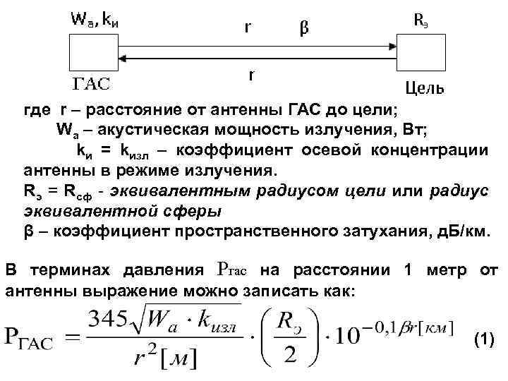 where R is the distance from the GAS antenna to the target; WA is the acoustic power of radiation, W; Ki \u003d Kizl - the axial concentration coefficient of antenna in radiation mode. RE \u003d RSF - equivalent target radius or radius of the equivalent sphere β is the coefficient of spatial attenuation, d. B / km. In terms of pressure of RGAS at a distance of 1 meter from the antenna, the expression can be written as: (1)
 We define the level of an echo signal from the target relative to the zero level P 0, using the relation (1) and prologate it with a decimal algorithm: we introduce the notation: - The level of the echo signal at the point of the arrangement of the GAS antenna, in the d. B; - level of radiation, in d. b; - This is the value expressed in the d. b and characterizing the reflectivity of the object.
 PR - standard losses in propagation, in d. B, taking into account the weakening of the signal when it propagates from the antenna of the GAS to the target and back taking into account the spherical law of distribution. Taking into account the introduced designations, the expression takes the form: NGAS \u003d UI + CC - 2 PR (2) of formula (2) is used to estimate the level of the echo signal from the target at the reception point in a homogeneous limitless environment without interference.
 Considering the processing of the utility signal of RGAS \u003d PC and interference with RP in GAS, and considering the recognition coefficient Δ, you can record the following expression of the RGAS \u003d PC \u003d Δ Rp Energy range equation of the CH (EE) mode: \u003d where k is the axial concentration coefficient of the antenna; Δf - frequency band (range) of the GAS reception path, Hz; F 0 is the average frequency of the range, to. Hz; β \u003d 0, 036 F 03/2 [to. Hz] - spatial attenuation coefficient, d. B / km.
 GAS on PN ANTENNA GAS UI PR SK UP POP OND ENGLIC RIGHT RENTIVE OF THE CHARGE OF CHA (EP) in symbolic form can be recorded (taking into account the sign "-") as: EP \u003d - (UI + SC - UP - PO + PN) \u003d 2 PR EP \u003d UE (interference level) \u003d
 Software (detection threshold) \u003d Mon (direction indicator) \u003d Active GAS: - GAS Distance Measurements - Gas Communication - GAS IMECTIVE - GAS MINISTANCE - GAS OF TORPED DEETS - GAS OF DEVELOUS SUPPLY SWORTS AND ADDITIONAL GAS - GAS OF LIGHTING AND DEVELOP - hydroacoustic lags - GAS side review

 The hydroacoustic armament of the NK consists of: ØGAK MGK-335 "Platinum" - a hydroacoustic complex of detection, targeting and communication; ØGAK MGK-345 "Bronze" - a hydroacoustic complex of detection, targeting and communications; ØGAK MGK-355 "Polynom" is a hydroacoustic complex of detection of the PL and issuance of target designation of anti-submarine arms; Ø Tags MG-332 "Argun", Gas MG-332 T "Argun-T" - a hydroacoustic station of detection and targeting for antique ships; Ø Tags MG-329 "Oka", Gas MG-329 m "Oka-M" - a lowered hydroacoustic station; Ø Tags MG-339 "Stemon" or Gas MG-339 T "Schend-T" - a hydroacoustic detection station, determination of coordinates, communication and identification;
 Ø Tags MG-79 or GAS MG-89 "Sulna" - a hydroacouatic station of detection of anchor and bottom mines; Ø Tags MG-7 "Bracelet" and Gas MG-737 "Amulet-3" - a hydroacoustic station of discovery of underwater sabotage forces and means; ØGas MG-26 "Host" or GAS MG-45 "Backgammon" - hydroacoustic and identification equipment. Ø Tags KMG-12 "Cassandra" - the instrument of classification of targets for hydroacoustic stations of surface ships when they work in active mode. Ø Tags MG-409 C is a system of passive detection of hydroacoustic buto. Ø Tags "Altyn" - equipment for measuring the vertical distribution of sound speed in water from the surface ship; ØGas Mi-110 km - the instrument of detection of the retaining trace of the APL.
 Fig. 1. Project rocket cruiser 1164 in service of the project 1164 Hydroacoustic weapons: Q GAK MGK-335 "Platinum"; Q GAS MG-7 "Bracelet" - 2 sets; Q GAS MG-737 "Amulet-3"; Q GAS KMG-12 "Cassandra". There is the following
 Fig. 2. Large anti-submarine ship of Project 1155 (1155. 1) The following hydroacoustic armament is in service with Project 1155: GAK MGK-335 "Platinum"; GAS MG-7 "Bracelet" - 2 sets; Gus "Altyn"; Gas Mi-110 km. In service of the project 1155. 1 is the following hydroacoustic weapons: GAK MGK-355 "Polin"; GAS MG-7 "Bracelet" - 2 sets; Gus "Altyn"; Gas Mi-110 km.
 Fig. 3. Project ship 956. Class: Rocket-artillery ship, subclass: Squaded Mission. 1 rank in service of the project 956 is the following hydroacoustic weapons: GAK MGK-355 "Polin"; GAS MG-7 "Bracelet" - 2 sets; GAS KMG-12 "Cassandra".
 Fig. 4. Project rocket boat 1241. 2 in service of the project 1241. 2 There is the following hydroacoustic weapons: GAK MGK-345 "Bronze"; GAS MG-45 "Backgammon";
 Fig. 5. Torpedic boat of the project 1241 in service of the project 1241 is the following hydroacoustic weapons: GAK MGK-345 "Bronze"; GAS MG-45 "Backgammon";
 Fig. 6. Small anti-submarine ship of the project 1124 in service of the project 1124 There is the following hydroacoustic weapons: GAS MG-339 "Stemon" or Gas MG-339 T "Schend-T"; Some projects are armed with GAC MGK-335 "Platinum"; GAS MG-322 "Argun" or Gas MG-322 T "Argun-T"; GAS MG-329 "Oka" or Gas MG-329 m "Oka-M"; GAS MG-26 "Host" or Gas MG-45 "Backgammon"; GAS KMG-12 "Cassandra". GAS MG-409 S.
 Fig. 7. Basic Trailer BTSCH project 1265 (Ave. 260, 270) in service of the project 1265 contains the following hydroacoustic weapons: GAS MG-79 or GAS MG-89 "Sulna"; Gus "Kabarga";
 Fig. 8. A large landing ship of the project of the 775 project 775 in service of the project 775 is the following hydroacoustic weapons: GAS MG-7 "Bracelet"; GAS MG-26 "Host" or Gas MG-45 "Backgammon".
 Hydroacoustic stations "Tamir-11" (1953) GAS for surface ships of small displacement The total number of devices - 17 Mass of the instruments - 1000 kg. Chief designer Vovochnoe B. N.
 Hercules hydroacoustic stations (1957) GAS for surface ships of medium and large displacement total number of devices - 30 Mass of instruments - 5800 kg Chief designer Umikov Z.N.
 Hydroacoustic stations "Mezen-2" (1963) GAS Detection of bottom min. Total number of devices Mass of instruments - 12 - 2100 kg Chief designer Low Novo I. I.
 Hydroacoustic stations "Kashalot" (1963) GAS for the search for sunken vessels The total number of instruments - 22 Mass of the instruments - 4000 kg (without zip) Chief Designer Timokov N. A.
 Hydroacoustic complexes "Rubin" (1964) GAK for multipurpose submarines Chief designer Ayalashkin E. I. Total number of devices - 56 Mass of instruments - 54747 kg
 Hydroacoustic stations "Titan-2" (1966) GAS for large anti-submarine ships Total devices Mass of instruments - 37 - 16000 kg Chief designer Harat G. M.
 Hydroacoustic stations "Argun" (1967) Gus for small anti-submarine ships Total devices Mass of instruments - 30 - 7600 kg with Zip Chief designer Ivanchenko V. P.
 Hydroacoustic stations "Sulna" (1969) GAS detection of the anchor and bottom mines The total number of devices mass of instruments - 20 - 3900 kg Chief Designer Lyashenko G. G.
 Hydroacoustic stations "Beech" (1971) GAS for research courts Total number of instruments Mass of instruments - 30 - 11,000 kg Chief designer Klimenko J. P.
 Hydroacoustic complexes "Platinum" (1972) GAK for surface ships of medium and large displacement Chief designer Klimovitsky L. D. Number of instruments - 64 Mass of instruments - 23 tons
 Hydroacoustic complexes "Polynom" (1979) GAK for the NC of large displacement Chief designer Soloviev V. G. Total number of instruments - 152 Mass of instruments - 72,000
 Hydroacoustic complexes "Star-M 1" (1986) Digital Guck for NK Middle Displacement Chief Designer Aleshchenko O. M. Total Number of Devices - 64 Mass Devices - 23000 kg
 Hydroacoustic complexes of "Kabarga" (1987) Gus Miniscovers for marine, basic and raid trails Total number of devices - 42 Mass of instruments - 8500 kg Chief designer Lyashenko G. G.
 Hydroacoustic complexes "Star M 1 -01" (1988) digital gas for surface ships of small displacement Chief designer Aleshchenko O. M. Total number of devices - 60 Mass of instruments - 16,500 kg
 Hydroacoustic Complexes "Star-2" (1993) Digital Guck for NC Large Displacement Chief Designer Borisenko N. N. Total Number of Devices - 127 Mass Devices - 77742 kg

 Perspective complexes Corvette Project 12441, which provides for the installation of gas "Zarya-2"
Chapter 1. Analysis of the main methods for determining the location of the source of navigation signals with ultra-thread-beads.
1.1. Setting the problem of developing a hydroacoustic navigation complex.
1.1.1. Experience of the IPMT in the development of rangefinder navigation systems.
1.1.2. The tasks of developing Hans-Uch.
1.2. Amplitude methods for determining the illumination information with small-sized (ultra-proposal) antennas.
1.2.1. Linear equidistant antenna.
1.2.2. Circular equidistant antenna.
1.2.3. Potential to accurately face amplitude delayers.
1.3. On the measurement of the phase shift of the Mesvd two tonal signals, distorted noise.
1.4. Estimated phase direction finding formulas in systems with simple configuration antennas.
1.4.1. Bay-element receiver.
1.4.2. Four-element receiver.
1.4.3. Six-channel phase delayer.
1.5. The method of depleting the source of navigation signals using circular discrete antennas with large number Elements.
1.5.1. The output of the estimated formulas and assessment of the error of the Ub-delayer with a circular base.
1.5.2. The direction-finding algorithms for the direction finder with a circular base, taking into account changes in the angle antenna orientation.
1.6. Findings.
Chapter 2. Statistical processing of information of the hydroacoustic navigation system with ultrashort base.
2.1. Solving the Task of Diapering based on statistical processing methods.
2.2. Diapering equations for multi-element antennas of various configurations.
2.2.1. Linear multi-element antenna.
2.2.2. Antenna with an arbitrary number of elements on a circular database.
2.2.3. Four-element antenna.
2.2.4. Circular antenna with an additional element in the center.
2.2.5. Two-cabin antenna.
2.2.6. Findings.
2.3. Features of processing a lot of frequency navigation signal.
2.4. Antenna configuration and potential accuracy assessment.
2.4.1. Antennas with a half-wave distance between the elements.
2.4.2. Rewrked antennas.
2.4.3. Select the review sector based on the antenna phasing.
2.5. Findings.
Chapter 3. Methodology for assessing the accuracy of navigation systems with ultra-screws base.
3.1. Assessment of the systematic component of the error of the definition of bearing.
3.1.1. Phase function of an imperfect multi-element receiving antenna.
3.1.2. Development of equipment for metrological certification of receiving multi-element antennas.
3.1.3. Experimental studies of the accuracy of antennas in laboratory conditions.
3.2. Estimates of the accuracy of the broadband direction finder (the study of the characteristics of the antenna for processing a multi-frequency navigation signal).
3.3. Experimental studies of the main characteristics of the ultra-circuit-base navigation system in the conditions of a small sea.
3.3.1. The method of certification of the system by comparing with the data of the certified navigation system (on the example of Hans-dB).
3.3.2. Methods for assessing the accuracy of angular measurements by rangefinder data.
3.3.3. Method of graduation of the ultra-voltage-base navigation system in full-scale conditions using the reference beacon.
3.3.4. Metrological rationale for graduation of the ultra-voltage-base navigation system according to Hans DB and GPS.
3.4. Assessment of the metrological characteristics of Hans-Ubb under the deep sea.
3.5. Findings.
Chapter 4. Methods for constructing and developing the main elements of the hydroacoustic communication system of the underwater apparatus. 146 4.1. The general approach to the assessment of the main parameters of the Gass for the anca.
4.1.1. General.
4.1.2. On the structure of the information symbol.
4.1.3. About synchronization.
4.1.4. On the selection of the pulse to evaluate the characteristics of the communication channel.
4.1.5. Processing data block.
4.1.6. Numerical modeling of the communication channel. 153 4.2.0 Development of broadband piezopraverters and antennas for Gass.
4.2.1. Broadband cylindrical piezo-methods.
4.2.2. Cylindrical piezopraverters with controllable characteristics
4.2.3. Broadband piston type piezo-formers.
4.2.4. About the electrical matching of piezopraverters in a wide frequency band.
4.2.5. On the energy efficiency of broadband transducers.
4.2.6. Characteristics of the developed antennas.
4.3. Multi-element receiver of Gass signals with adaptive control of the HN according to the direction finder of the navigation system.
4.3.1. Data processing.
4.3.2. Characteristics of UBB antenna when receiving communication system signals.
4.4. Experimental study of the non-coherent multi-frequency communication system with amplitude correction of the gear ratio of the channel.
4.4.1. Algorithm for processing a multi-frequency signal.
4.4.2. Structural circuit of communication system.
4.4.3. Experimental studies of the elements of the hydroacoustic communication system in the conditions of a small sea.
4.5. Findings.
Chapter 5. Development of Doppler Lag as part of the onboard navigation system of the underwater apparatus.
5.1. Antennas.
5.2. Spectral processing of short pulse signals.
5.3. Structure and circuitry.
5.4. Foreign studies of the characteristics of lag as part of the anca.
5.5. Findings.
Chapter 6. Technical implementation and experience of the practical application of hydroacoustic means of navigating underwater robot. 207 6.1. Technical implementation of the hydroacoustic navigation system with ultra-screws base.
6.1.1. Structural scheme of Hans-ukb.
6.1.2. Features of building hardware.
6.1.3. Reception Antenna Navigation System.
6.1.4. Data processing.
6.1.5. User interface.
6.1.6. Software.
6.1.7. Foreign tests and practical operation of Hans-Ukb.
6.2. Specifications Kit equipment Gass.
6.2.1. Main characteristics.
6.2.2. Principle of operation.
6.2.3. Structural diagram of the receiver.
6.2.4. The structure of the Gass signal.
6.2.5. The results of marine tests in the deep sea.
6.3. Hydroacoustic navigation complex.
6.3.1. The composition and purpose of the ship navigation complex.
6.3.2. Technical proposals for the development of a combined navigation and management system.
6.4. Complex tests of hydroacoustic navigation and experience in their use during real work.
6.4.1. Complex navigation tests.
6.4.2. Experience in practical use of hydroacoustic navigation tools during real search engines.
Recommended list of dissertations
Development of methods and algorithms for one-way navigation of autonomous uninhabited submarines 2013, Candidate of Technical Sciences Dubrovin, Fedor Sergeevich
Methods for processing hydroacoustic signals received in the zone of Fresnel receiving and emitting systems 2010, Doctor of Technical Sciences Kolmogorov, Vladimir Stepanovich
Underwater and navigation using an electromagnetic field 2006, Doctor of Technical Sciences Shibkov, Anatoly Nikolaevich
Methods and systems for improving sailing safety based on hydroacoustic navigation devices with a linear base of directional receivers 2006, Doctor of Technical Sciences Zavyalov, Viktor Valentinovich
Navigation of the autonomous underwater apparatus with the help of an inerial inertial navigation system 2017, candidate of physical and mathematical sciences Filatova, Gusel Amirovna
Similar dissertation work in the specialty "Acoustics", 01.04.06 CIFRA VAC
Development of the method of increasing the accuracy of the positioning of underwater objects 2013, Candidate of Technical Sciences Heads, Alexander Alexandrovich
Parametric method of controlled transformation of hydroacoustic fields of noise emission of research and fishing vessels, methods and systems of their measurement based on nonlinear acoustics patterns 2002, Candidate of Technical Sciences Khaliulov, Fargat Amershanovich
Development of information processing algorithms in multi-title systems using a quick spectral analysis of signals 2005, Candidate of Technical Sciences Davletkaliyev, Roman Kuanishevich
Methods and means of navigation support of aircraft and air traffic control based on satellite technologies 2004, Doctor of Technical Sciences Slepchenko, Peter Mikhailovich
Theory and methods of designing ultra-wideband antenna systems for radio-fitting inpatient and mobile basing 2011, Doctor of Technical Sciences Rebovsky, Yuri Anatolyevich
Conclusion of dissertation on the topic "Acoustics", Matvienko, Yuri Viktorovich
Main results:
1. The principles of constructing ultra-dotted systems were investigated and an analysis of the basic methods for determining the angular position of the source of tonal and broadband navigation signals during processing information of small-sized receiving antennas were studied.
Estimated expressions were obtained and the direction finding characteristics of amplitude delayrs with total and difference data processing were investigated.
The low potential accuracy of the simplest configuration systems containing one, two or three pairs of orthogonal receivers are noted with phase data processing methods and the need for complication of systems to increase accuracy is noted.
A method for the direction finding the source of tonal signals based on the use of antennas with a large number of receivers tightly placed on a circular base with the definition of the cumulative phase is also proposed, whose error can potentially be reduced to 0.1Gradus.
The calculated formulas and on the example of circular antennas with a large number of items are shown the connection of the course sensor data, roll and differential and their errors on the value of the measured navigation parameters and their errors.
Based on the maximum truthful method, the task of statistical processing of navigation data was solved when using discrete antennas of arbitrary configuration. In this case, the evaluation of the desired parameters is determined by joint processing of all pairs of channels taken with different scales. Weighting coefficients contain as a geometric component, equal to the derivative of the phase function according to the measured parameter and the energy equal to the signal-to-acting signal in the channel.
The estimated relationships are derived for the definition of bearing and the damping error for a number of the most common antenna configurations: linear, circular, combined.
A phase direction finder was developed based on the use of circular antennas of a large wave size with a limited number of elements.
The technology of reducing the number of processing channels with the preservation of the angular resolution is substantiated by separating the diapering procedure into two stages: coarse direction finding to determine the viewing sector and the exact solution of the bearing equation at a given initial approximation.
The possibility of permission of phase ambiguities arising during the operation of a sparse antennas by the methods of amplitude direction finding was justified.
Theoretically substantiated the achievement of the angular resolution of 0.1-0.2 degrees with the number of channels 6-8 and the wave size of the antenna 3-5 of the wavelengths of the navigation frequency.
Relations for calculating the bearing of a small-sized discrete antenna, the propagation time of the acoustic signal on the aperture of which is comparable to the average frequency of the received spectrum.
2. Research methods for assessing the accuracy of Hans UKB accuracy and developed methods for measuring their characteristics in laboratory and tool conditions.
To describe a discrete multi-element antenna, a vector function was proposed, each component of which describes the dedicated element of the antenna dependence of the phase of the acoustic signal from the direction of its arrival. The exact (experimental) definition of the function is mandatory when solving the task of delaying the navigation object.
A stand for certification of multi-element antennas, which is installed in a specialized hydroacoustic basin and includes a source of adjustable signals and a receiving system with a precision rotary platform and multichannel phase measurement equipment for radio pulse type signals.
An antenna certification technology has been developed, which consists in experimentally measuring the phase function of the antenna, the determination of analytical functions that approximate the obtained data and the use of them in solving the direction-finding equations, with the tabulation of the difference of the origin of the bearing and its true (installation) value in the form of an assessment of the systematic component of the error.
Multi-element receiving antennas for active samples of systems are developed and investigated, which provide the value of a systematic error around 0.5 Aradus.
A comparative analysis of the work of Hans dB and UBB in the conditions of a small sea with a fixed installation of the ACB receive antenna is carried out.
Analyzed the method for estimating relative angular measurements based on the processing of rangefinder data.
The method of certification of the UCB system in the small sea using the reference beacon based on the processing of rangefinder data is substantiated. It is shown that with the relative error of measuring the range, a few tenths percent, an error of the design value of the bearing for annea, which makes movement around UKB - antenna and a lighthouse on a closed trajectory, does not exceed one degree.
An analysis was carried out and the accuracy characteristics of the UCB system based on the results of work in the conditions of the deep sea were determined. As the reference data, the DB HANS data was used, the onboard navigation system and the depth sensor, rangefinder data. The feasibility of analyzing the differential variability of the rangefinder data to identify individual fragments of the ANPA movement trajectory and the possibility of reasonable averaging of angular data with the trajectory processing are shown. As a result of the analysis, the conclusion is justified about the error of angular measurements of about 0.5.
The technique of eliminating phase ambiguities arising from increasing the size of the measuring base is substantiated and experimentally tested by the statistical processing of multi-frequency signals.
The multi-element receiving antenna and the equipment of the radiation (reception) of complex signals were developed and experimentally studied, estimates of the system error were made, which constitute the tenths of hail.
3. The methods are investigated and means of a high-speed information transmission system for the hydroacoustic channel from the board of ancpa to the providing vessel.
Studies of construction of broadband piezo-converters were developed and specialized cylindrical and rod converters were developed with special orientation characteristics designed to work in communication system equipment: a highly efficient cylindrical converter was proposed with a bandwidth to three octave using thin matching layers of the horn configuration, which meets the requirements for work in a small sea; A variety of resonant converter is proposed for radiation and reception of multi-frequency signals, made in the form of a set of coaxial piezocylinders; Piston piezopraverters are proposed with a single-sided type HN to work in a vertical signal propagation channel.
Analyzed the structure of the data transmission system for the multipath channel of communication with the adaptation of the processing circuit through the data block of the final length. The transmission of the information block is preceded by the procedure for setting the receiver settings, the temporary block size is determined current status Communication channel. The methods of numerical modeling analyzed the features of selection of connected signals and shows the expediency of using the signal to combined phase and frequency manipulation.
A methodology for estimating the pulse characteristics of the communication channel and refinement of the moment of synchronization by transmitting and processing a series of pulses of the alternating phase is proposed.
A diagram of receiving signaling system signals of a multi-element navigation antenna with the realization of the spatial filtering of the direct beam under the conditions of multipath distribution based on data on the angular position of the source of signals and interference received during the operation of Hans UKB is proposed.
Studies have been made and justified the possibility of transmitting information in a multi-frequency communication channel with a preliminary alignment of the through amplitude frequency response of the channel and selecting the current message based on a comparative analysis of energy in each frequency channel. Experimental studies of such a processing system in a very small sea confirmed the possibility of using equipment for transmitting graphic images at a speed of about 3000bit / s at a low probability of errors.
4. For onboard navigation, the underwater robot is designed and integrated into the complex Doppler Lag.
Studies completed and developed specialized lag antennas with high echo sensitivity obtained due to the optimal acoustonic mechanical coordination of the antenna's piezo-methods with a working environment.
To increase the speed of lag, a method of spectral processing of short pulse signals is proposed and implemented, providing high frequency resolution due to the formation of long quasi-coherent implementations of reflected signals. The method allows you to determine the speed components with the minimum dispersion in one second.
Designed and used as part of the ANPA Experimental Sample Doppler Lag
A technique of graduation of lag in full-scale conditions was developed by calculating the ANPA velocity on the range finding data of Hans.
5. Designed, tested and tested in real operations a hydroacoustic navigation complex, which ensures the formation of a navigation information picture of the movement of the mission aboard the providing vessel and anca, consisting of hydroacoustic navigation tools, transmission of information and measurement of absolute speed.
Designed, tested in a small and deep sea and integrated into the Navigation Complex of the Hans UKB, which includes: a synchronized source of the navigation signal at the facility, a ship processing complex with a receiving antenna on a cable cable, GPS receiver. The system has the following characteristics: range - 6-10 km; The error of measurement of the bearing is less than 1 degrees; The limit measurement error is 0.5%. Experimentally confirmed the possibility of operating the system in the position of the position of the anca, which makes a long transition along the extended object with the movement of the providing vessel and towing the receiving antenna at a speed of up to 5 nodes.
Designed, tested and used as part of a hidden apparatus a high-frequency system of navigation ukb with the placement of the source on board the vessel, and the receiver on the machine.
Designed and tested in the composition of the hydroacoustic means of navigation and information support, an APA equipment transmission equipment for operational control of the state of surveillance and search work in the conditions of the deep sea and the vertical communication channel. The equipment provides data transmission at a speed of 4000bit / s, with a probability of errors about one percent, which ensures the transmission of the image frames for 45c.
Designed, tested and integrated into the onboard navigation system Doppler Lag, providing the measurement of the absolute velocity of the anca in the range of speeds 0-2m / s with an error of 1-2 cm / s.
The technology of application of the navigation complex is proposed:
Hans DB - for multiple Runs of the anca in the dedicated areas with searching in areas with increased requirements for accuracy.
Hans UKB if there is no longer transitions when tracking extended objects or moving purposes, in case of emergency starts of the anca, in the case of secretive launches.<
To with the calculation of the trajectories on the number - when the anca is released at a specified point, when adding to the use of TV systems.
The successful work of the complex in the composition of the anc does not demonstrate when performing real search engines in the ocean.
Gratitude.
In conclusion, I want to express deep appreciation to all employees of the IPMT, who participated in the development and testing of hydroacoustic systems of underwater vehicles. Special thanks to Academician Ageev M.D., the heads of the Kaskin region, B. A. and Rylov N.I.
Conclusion
References dissertation research doctor of Technical Sciences Matvienko, Yuri Viktorovich, 2004
1. Ageev m.d. Modular Autonomous Unmanned Vehicle of 1.tp. - MTS Journal, 1996, Vol. 30, 1, p. 13-20.
2. Autonomous uninhabited underwater vehicles. Under the general ed. Acad. Ageeva m, d. - Vladivostok, Dalnawka, 2000, 272c.
4. R.Babb. AUV Navigation for Underwater Scientific Surveys. Sea Technology, 1990, December, P.25-32.
6. J. Romeo, G. Lester. Navigation IS Key to Auv Missions. Sea Technology, 2001, December, P.24-29.
7. Borodin V.I., Smirnov G.E., Tollova H.A., Yakovlev G.V. Hydroacoustic navigation tools. L., Shipbuilding, 1983, 262c.
8. Miln P.h. Hydroacoustic positioning systems. L., Shipbuilding, 1989,316c.
9. Gestone J.A., Cyr R.J., ROESLER G:, George E.S. Recent Developments in Acoustic Underwater Navigation. Journal of Navigation, 1977, V.30, 2, P.246-280.
10. Boldrev B.C. Precision methods. Definitions of coordinates during hydrophysical work in the open sea. Shipbuilding abroad, 1980. №2. C.29-42.
11. Kyslov A. F., Postnikov I.V. Accuracy characteristics of beacon navigation systems with a long acoustic base. Tez. Dokl. 2 All-Union. Conf. Research and development of the ocean, L., 1978. Sme.2, P.95-96.
12. Kasatkin B.A., Kobidze V.V. Features of the hydroacoustic navigation in the shelf zone. In Sat Underwater devices and their systems, from dffa, Vladivostok, 1977, from 84-88.
13. Kasatkin B.A., Kobidze V.V. Hydroacoustic synchronous rangefinder navigation system. Patent R.F. G01S 9/60, № 713278, 1978.
14. Smirnov G.E., Tollova N.A. Navigation systems with hydroacoustic beacons. Shipbuilding abroad. 1980, №9, p.45-54.
15. K. Vestgard, R. Hansen, V. Jalving and H.Pedersen. The Hugin 3000 Survey AUV -Design and Field Results.- / Underwater Intervention 2001 /.
16. T. Martin and G. Pilgrim. Survey Challenges in Deepwater Acoustic USBL Positioning of Towed Or Tethered Underwater Vehicles. .- / underwater intervention 2001 /.
17. Hubert Thomas, Eric Petit. From Autonomous Underwater Vehicles (AUV) to Supervised Underwater Vehicles (SUV). Oceans-97.
18. Paramonov A.A., Klyuev M.C., Storozhev P.P. Some principles for constructing hydroacoustic navigation systems with a long database. VII interddes Scientific school. conf. "Modern methods and means of oceanological studies", Moscow, 2001, p.244-245.
19. Paramonov A.A., Afanasyev V.N. Hans-M hydroacoustic navigation system. VI interday Scientific school. conf. "Modern methods and means of oceanological research", Moscow, 2000, p. 100-112.
20. Ageev MD, Blidberg D.R., Kiselev Ji.B., Rylov N.I., Shcherbatyuk A.F. State and prospects for the development of underwater robotics. Sea technologies, Vladivostok, Dalnalock, 2001, Isk.4, p.6-23.
21. Ageev MD, Casatkin B.A., Kiselev L.V., Molokov Yu.G., Nikiforov V.V., Rylebov N.I. Automatic underwater vehicles. L., Shipbuilding, 1981.248 p.
22. J. MANLEY. Autonomous Underwater Vehicles for Ocean Exploration. 0Ceans-2003, p.327-331.
23. Kobidze V.V. The speed of propagation of hydroacoustic signals in the range of ranges. Preprint, Vladivostok, that Fedz Academy of Sciences of the USSR, 1979, 37c.
24. Kobidze V.V. The study of the accuracy of the hydroacoustic rangefall. - Author of the dissertation KF-m.n. Vladivostok, that DVTC of the USSR Academy of Sciences, 1981, 26c.
25. Xavier Lurton, Nicholas W. Millard. The Feasibility Of A Vaiy-Long Baseline Acoustic Positioning Sistem for AUV. Proceeding of Ocean-94, Brest-France, 1994, Vol.3, PP. 403-408.
26. Kasatkin B.A., Kosarev G.V. Feature of Development of the APS for Very Long Range AUV. Proceeding of Ocean-95, San-Diego, October 1995, V. I, p. 175-177.
27. Kasatkin B.A. Hydroacoustic synchronous rangefinder long-range system. Patent R.F. G01S 15/08, № 2084923, 1995.
28. Acoustic Positioning. www. Mors.fr.Product.
29. Combined Range and Bearing Navigation Sensor. Model NS-031. -www. Sonatech.com.Product.
30. Kasatkin B.A. Hydroacoustic synchronous rangefinder navigation system. Patent R.F. G01S 15/08, № 2084924, 1995.
31. D. Thomson, S. ELSON. New Generation Acoustic Positioning Systems. 0Ceans-2002, p.1312-1318.
32. PROGRAMMABLE GENERIC TRANSPONDER AND SUPER SUB-MINI TRANSPONDER / RESPONDER, TYPES 7971/7977 / 7978,7970 / 7973 WWW.SONARDYNE.CO.UK
33. B. MANSON. Wide-Area Positioning with LM Accuracy. -INternational Ocean Systems, Desember 2001, p. 15-19.
34. Kasatkin B.A., Kosarev G.V. Physical bases of acoustic rangefall. Bulletin of DVO R And998, №3.c.41-50.
35. Kobidze V.V. Models of errors and algorithms for processing range-facing information in hydroacoustic navigation systems. Predprint, Vladivostok, that DVTC of the USSR Academy of Sciences, 1979, 42c.
36. Kasatkin B.A. Invariant characteristics of the sound field in the layered ocean. Dokl. Academy of Sciences of the USSR, 1986, 291, №6, p. 1483-1487.
37. M.DEFFENBAUGH, J.G. Bellingham, N. Schmidt. The Relationship Between Spherical and Hyperbolic Positioning. Proceeding of Ocean-96,
38. Kasatkin B.A., Kosarev G.V. Analysis of the accuracy of measurement of the coordinates of the beacon-respondents of the hydroacoustic navigation system. Sea technologies, Issue.1. Vladivostok, Dalnaka, 1996, p.60-68.
39. Kasatkin B.A., Kosarev G.V. The use of the traverse method to determine the absolute coordinates of the respondent beacons. Sea technology, vol.2. Vladivostok, Dalnaka, 1998, p.65-69.
40. J. Opderbecke. AT-SEA Calibration of A USBL Underwater Vehicle Positining System. -Oceans "2000.
41. POSIDONIA 6000. UNDERWATER ACOISTIC POSITIONING SYSTEM. www.ixsea-ceano.com.
42. NEWSLETTER. Kongsberg Simrad. ISSUE NO.2-2000. www.kongsberg-simrad.com.
43. K. Vestgard, R. Hansen, B.Jalving, O.A. Pedersen. THE HUGIN 3000 SURVEY AUV. Desigh and Field Results. 0ceans "2001.
44. LXT Low Cost Tracking System. www.ore.com.
45. Thomas C. Austin, Roger Stokey, C. Von Alt, R. Arthur, R. Goldborough. Rats, A Relative Acoustic Tracking System Developed for Deep Ocean Navigation- Oceans "97.
46. \u200b\u200bThomas C. Austin, Roger Stokey. Relative Acoustic Tracking.- Sea Technology, 1998, March, P.21-27.
47. M. Watson, C. Loggins and Y.T. Ochi. A New High Accuracy Super Short Base Line (SSBL) System. UNDERWATER TECHNOLOGY, 1998, P.210-215, Tokyo, Japan.
48. James E. Deveau. Underwater Acoustic Positioning Systems. Oceans-95, Vol.1, p. 167-174, San Diego, USA.
49. NAUTRONIX. ATS Accurate Positioning www.nautronix.com
50. Yin Dongmei, Song Xinjian, Feng Haihong. The Key Technology to Implement An Underwater Object Tracking and Positioning System. -The 3-D International Workshop Harbin, China, 2002, P.65.
51. Yin Dongmei, Song Xinjian, Feng Haihong. Designing An Underwater Acoustic Positining System. The 3-D International Workshop Harbin, China, 2002, P.43.
52. Komulakov B.A. Hydroacoustic systems with beacons by respondents for tracking towed underwater complexes. - Shipbuilding, 1997, No. 6, p.39-45.
53. Paramonov A.A., Nosov A.V., Kuznetsov V.N., Dreuchsev S.A., Klyuev M.S., I I
54. Storozhev P.P. On improving the accuracy of the hydroacoustic navigation system with a sulture core base. VII International Confirm. According to Oceanology, M., 2001, P.80-81.
55. Bogorodsky A.V., Koryakin Yu.A., Ostrukhov A.A., Fomin Yu.P. Hydroacoustic technology research and ocean development technique. VII International Confirm. Oceanology, M., 2001, p.266-269.
56. Zlobina N.V., Kamenev S.I., Kasatkin B.A. Analysis of the error of the hydroacoustic navigation system with ultra-screws base. In Sat Underwater robots and their systems. Issue 5,1992, Vladivostok, IPMT DVO RAS, p.116-123.
57. Kasatkin B.A., Kulinchenko S.I., Matvienko Yu.V., Nurgaliev R.F. The study of the characteristics of the phase direction finder for UBB-Hans.- in Sat. Underwater robots and their systems. VISH.6,1995, Vladivostok, Dalnawka, P.75-83.
58. Kasatkin B.A. Assessment of the error of the Ub-delayer with a circular base. In Sat Sea technology. Vol. 1,1996, Vladivostok, Dalnawka, P.69-73.
59. Kasatkin B.A., Matvienko Y.V. The method of determining the bearing on the source of radiation and the device for its implementation. RF Patent No. 2158430, Bul. Isoble .№33, 2000
60. Matvienko Yu.V., Makarov V.N., Kulinchenko S.I. , Nurgaliyev R.F., Rylov R.N. Hydroacoustic navigation system with ultrashort base. Sea technologies, Vladivostok, Dalnalock, 2000, discharge, s. 102-113.
61. Matvienko Yu.V. Data processing in a UB-direction finder based on an imperfect multi-element antenna. VIII interddes Scientific school. conf. "Modern methods and means of oceanological research" Moscow, 2003, Part 1, p.24-25.
62. John G. Proakis. Digital Communications. Publishing House Of Electronics Industry, China, Beijing, 2000, 928p.
63. M.Stojanovic. Recent Advances in High-Speed \u200b\u200bUnderwater Acoustic Communications. Ieee Journal Oceanic Engineering, Vol.2 L, NO.2, 1996, p. 125-136.
64. M.Stojanovic, J.Catipovic, J.Proakis. Phase Coherent Digital Communications for Underwater Accountic Channels. Ieee Journal Oceanic Engineering, Vol. 19, no. 1, 1994, P.100-111.
65. Stojanovic M., J.A. Catipovic and J.g. Proacis Reduced Complexity Spatial and Temporal Processing Of Underwater Acoustic Communication Signals.- J. Acoust. SOC. Am., 98 (2), pt.l, aug. 1995, P.961-972.
66. J. Labat. Real Time Underwater Communication. Ocean-94, Brest, France, Vol.3, P.501-506.
67. A.G. Bessios, F.M. Caimi. MultiPath Compensation for Underwater Acoustic Communication. Ocean-94, Brest, France, Vol.1, p.317-322.
68. Lester R. Leblanc. Spatio-Temporaal Processing of Coherent Acoustic Communication Data in Shallow Water. IEEE J. Ocean. Eng. Vol.25, NO 1, Jan., 2000, p. 40-51.
69. Lester R. Leblanc. Adaptive Beamformer for Communication in Shallow Water
70. B. Geller, V. Capellano, J.M. Brossier, A. Essebbar and G. Jourdain. Equalizer for Video Rate Transmission in MultiPath Underwater Communication. IEEE J. Ocean. Eng. Vol.21, NO 2, Apr., 1996, p. 150-155.
71. Billon D., Quellec B. Performance of High Data Acoustic Underwater Communication Systems using Adaptive Beamforming and Equalizing. Ocean-94, Brest, France, Vol.3, P.507-512.
72. R. coates. Underwater Acoustic Communication. Sea Technology, 1994, NO. 6, p. 41-47.
73. A. Zielinski, Young-Hoon Yoon, Lixue Wu. Performance Analysis of Digital Acoustic Communications in Shallow Water Channel. IEEE Journal Oceanic Engineering, Vol.20, No.4, 1995, P.293-299.
74. L. Wu and A. Zielinski. Multipath Rejection Using Narrow Beam Acoustic Link. -Oceans-88, Baltimore, P.287-290.
75. Wang C.h., Zhu Min, Pan Feng, Zhang X.J., Zhu W.Q. MPSK Underwater Acoustic Communication Modem.
76. ATM 870 SERIES. Acoustic Telemetry Modems. Users MANUAL. - DataSonics, FeBry 1999.
77. K. Scussel, J.Rice, S. Merriam. A new MFSK Acoustic Modem for Operation in Adverse Underwater Channels. Oceans-97, Halifax.
78. J. Catipovic, M. Deffenbaugh, L.Freitag, D. Frye. An Acoustic Telemetry System for Deep Ocean Mooring Data Acquisition and Control. Oceans-89, p. 887-892.
79. F. Caimi, D. Kocak, G. Ritter, M.schalz. COMPARISON AND DEVELOPMENT OF COMPRESSION ALGORITHMS FOR AUV TELEMETRY. Recent Advancements.
80. P.I. Penin, E.A. Tsellev. On some approximations used in the calculation of hydroacoustic communication channels. Far Eastern acoustic compilation, vol. 1, Vladivostok, 1975, p. 15-18.
81. P.I. Penin, E.A. Tsellev, A.V. Shulgin. Energy calculation of hydroacoustic communication channels. Far Eastern acoustic compilation, vol. 1, Vladivostok, 1975, p. 19-23.
82. Svverkin E.I. Hydroacoustic telemetry in oceanology. - L. 1978. 149c., Publishing House of Lenuniversity.
83. V.P. Kodanev, S.P. Piskarev. Methods for optimizing the characteristics of the system of transmission of digital information on the hydroacoustic channel under conditions of single-rigging reception. Acoustic magazine, 1996, Volume 42, №4, p.573-576.
84. Yu.V. Zakharov, V.P. Kodanev. The noise resistance of the adaptive reception of complex acoustic signals in the presence of reflections from the ocean boundaries. Acoustic magazine, 1996, Volume 42, №2, p.212-219.
85. Yu.V. Zakharov, V.P. Kodanev. Adaptive reception of signals in the hydroacoustic communication channel with regard to Doppler scattering acoustic magazine, 1995, Volume 41, No. 2, p.254-259.
86. Yu.V. Zakharov, V.P. Kodanev. Experimental studies of an acoustic information transmission system with noise-like signals. Acoustic magazine, 1994, volume 40, №5, p.799-808.
87. Volkov A.V., Kuryanov B.F., Penkin M.M. Digital hydroacoustic communication for oceanic applications. VII International Confirm. Oceanology, M., 2001, p.182-189.
88. L.R. Leblanc and R.R.J. Beaujean. Spatio-Temporaal Processing of Coherent Acoustic Communication Data in Shallow Water. Ieee Journal Oceanic Engineering, Vol.25, NO. 1, 2000, P.40-51.
89. M. Suzuki, K. Nemoto, T. Tsuchiya, T. Nakarishi. Digital Acoustic Telemetry of Color Video Information. Oceans-89, P.893-896.
90. R. Rowlends. F.Kvinn. Limits of the speed of information transfer in the hydroacoustic telemetry. - In the CN. Underwater acoustics, Moscow, world, 1970, p.478-495.
91. Ridges A.A. Ship speed meters. Ji., Employment, 1978, 286c.
92. K.V. Jorgenson, B.L. Grose, F.A. Crandal. Doppler Sonar Applied to Precision Underater Navigation. Ocean-93, Vol.2, P.469-474.
93. Kasatkin B.A., Zlobin H.B., Kasatkin S.B. Analysis of the characteristics of the piezo-forming agent of the phased antenna of Doppler lag. In Sat Sea technology. Vol. 1,1996, Vladivostok, Dalnawka, P.74-83.
94. R. Pinkel, M. Merrefield and J. Smith. Recent Development in Doppler Sonar Technology. . Ocean-93, Vol.1, P.282-286.
95. RDI WORKHORSE NAVIGATOR DVL. www.rdinstruments.com.
96. Demidine B.M., Zolotarev B.B., Matvienko Yu.V., Plotsky V.D., Servetnikov M.I. Hydroacoustic navigation system. Tez. Foundation 22 Scientific and Technology. Konalnevost. Polytech. Inst. Vladivostok, 1974.
97. Demidin V.M., Matvienko Yu.V., Plotsky V.D., Servertovikov M.I. Navigation system of the underwater apparatus "Skat". Tez.Donal 1 All-Union. Conf. According to the study and development of the world's ocean resources. Vladivostok, 1976.
98. Dorokhin K. A. Presentation of the data of the hydroacoustic navigation system. In Sat Underwater robots and their systems. Issue 5,1992, Vladivostok, IPMT DVO RAS, P.94-100.
99. Dorokhin K. A. Hardware and software of the ship block of the hydroacoustic navigation system. In Sat Underwater robots and their systems. Issue 5,1992, Vladivostok, IPMT DVO RAS, p. 101-109.
100. Dorokhin K.A. Controller of the hydroacoustic navigation system. In Sat Underwater robots and their systems. 1990, Vladivostok, IPMT DVO Academy of Sciences of the USSR, with. 102108.
101. Sosalin Yu.G. Theoretical bases of radar and radio navigation. M., Radio and Communication, 1992, p. 134.
102. Matvienko Yu.V. On the accuracy of amplitude direction finders. Limit technologies, Vladivostok, Dalnawka, 2003, issue 5, p.56-62.
103. Smartyshev MD, Dobrovolsky Yu.Yu. Hydroacoustic antennas. Directory.-Ji., Shipbuilding, 1984, p. 171.
104. Ya.D. Shirman, V.N. Manjo. Theory and technique of processing radar information on the background of interference. M., Radio and Communication, 1981, 416c.
105. J. Bendat, A. Pirsol. Applied analysis of random data. Moscow, Mir, 1989, 542c.
106. Kenneth S. Miller, Marvin M. Rochwarger. Acovariance Approch to Specrtral Moment Estimation. Ieeetransactions on Information Theory, Sept. 1972, p.588-596.
107. Weiqing Zhu, Wen Xu, Jianyun Yu. ERROR ESTIMATION OF PULSE PAIR CORRELATION DIFFERENTIAL PHASE ESTIMATOR OF SONAR ARRAY. Oceans-96.
108. Zhu Weiqing, Wang Changhong, Pan Feng, Zhu Min, Zhang Xiangjun. Spectral Estimate in ADSP. Oceans-97.
109. Development of devices, devices and principles for the construction of hydroacoustic systems of the underwater apparatus. - // Report on the OKR "Mayak-IPMT" //, scientific. Hands. Matvienko Yu.V. Vladivostok, GFC NGO Delstandart, 1992, 190s.
110. Matvienko Yu.V., Rylov R.N., Rylov N.I. Development of a receiving antenna of a phase baaptic hydroletor of the side view. VII interddes Scientific school. conf. "Modern methods and means of oceanological research", Moscow, 2001, p.
111. Development and creation of an autonomous uninhabited underwater apparatus with an increased distance and autonomy. // scientific. Hands. Academician Ageev MD, P. Artist Matvienko Yu.V., Vladivostok, IPMT DBO RAS, 2001, No. State Ros. 01.960.010861.
112. Special reports on OCC "K -1R" // Chief Designer Academician Ageev MD, Deputy Gl. Const. Matvienko Yu.V. Vladivostok, IPMT DVO RAS, 1998-2003.
113. G. Korn, T. Corn. Handbook of Mathematics.- Moscow, Science, 1970s, 720s.
114. Matvienko Yu.V. Statistical processing of the information of the hydroacoustic navigation system with ultra-screws base. In Sat Sea technology. Issue.2,1998, Vladivostok, Dalnawka, P.70-80.
115. Rylov N.I. On the definition of navigation parameters in UKB HANS according to a multi-element antenna. In Sat Marine technologies, Vladivostok, Dalnawka, 2003, issue 5, p.46-55.
116. A. STEELE, S. BYRNE, J. Riley, M. SWIFT. Performance Comparison of High Resolution Bearing Estimation Algorithms using Simulated and Sea Test Data. Ieee Journal Oceanic Engineering, Vol.l8, No.4, 1993, P.438-446.
117. P. Kraeuther, J. Bird. Principal Components Array Processing for Swath Acoustic Mapping. Oceans-97.
118. Super-high integrated circuits and modern signal processing. Ed. S. Guna, X. Whitehaus. T. Kailat., Moscow, Radio and Communication, 1989, 472c.
119. Marple Ml. C.ji. Digital spectral analysis and its application. M. World., 1990, 584c.
120. A. STEELE, C.Byrne. High Resolution Array Processing using implicit Eigenvector Weighting Techniques. Ieee Journal Oceanic Engineering, Vol. 15, no. 1, 1990, p.8-13.
121. R. ROY AND T. KAILATH. ESPRIT- ESTIMATION OF SIGNAL PARAMETERS VIA ROTATIONAL INVARIANCE TECHNIQUES. Ieee Transactions on Acoustics, Speech and Signal Processing, Vol.37, No.7, 1989, P.984-994.
122. GAO HOGZE, XU XINSHEG. Researching on Phase Detection Method of Multi-Beam Swath Bathymetry System. IWAET-99, Harbin, China, 1999, p. 198-203.
123. Kinkulkin I.E., Rubtsov V.D., Fabrik M.A. Phase method for determining coordinates. M., 1979,. 280s.
124. Matvienko Yu.V., Makarov V.N., Kulinchenko S.I., Rylov R.N., a delayer of broadband navigation signals. In Sat Sea technologies, Vladivostok, Dalnalock, 2000, discharge, s. 114-120.
125. Matvienko Yu.V., Makarov V.N., Kulinchenko S.I., Nurgaliyev R.F., Rylov R.N., Kasatkin B.A. The delayer of the hydroacoustic navigation system with ultra-screws base. RF Patent №2179730, Bul. Isoble .№5, 2002
126. V. Douglas and R. Pietsch. Optimal Beamforming Techniques for Imperfectly Calibrated Arrays. Proceeding of Ocean-96,
127. MD Ageev, A.A. Boreyko, Yu.V. Vaulin, B.E. Gornak, B.B. Zolotarev, Yu.V. Matvienko, A.F. Shcherbatyuk Upgraded TSL Submarine to work on the shelf and in tunnels. - in Sat. Sea technologies, Vladivostok, Dalnawka, 2000, discharge, p.23-38.
128. Matvienko Yu.V., Makarov V.N., Kulinchenko S.I. On the selection of the structure and characteristics of the equipment of the hydroacoustic communication channel of the underwater machine. - Sat. Marine technologies, Vladivostok, Dalnawka, 1996, Issue.1, p.84-94.
129. Matvienko Yu. V. Estimation of the main parameters of the hydroacoustic communication system for the underwater machine. In Sat Sea technology. Stage.4,2001, Vladivostok, Dalnawka, S.53-64.
130. Forecast research on the creation of a unified range of managed autonomous apparatuses in order to increase the efficiency of lighting systems of underwater, navigation, anti-submarine and anti-mining struggle
131. Navy. // Report on NIR "Centurion-DVO" //, scientific. Hands. Academician Ageev MD, P. Artist Matvienko Yu.V., Vladivostok, IPMT DVO RAS, 1996
132. Theoretical foundations of radar. Ed. V.E. Dulevich., Moscow, Soviet radio, 1978, 608c.
133. Kasatkin B.A., Matvienko Yu.V. To the assessment of the broadband of low-frequency cylindrical piezo-converters. Acoustic magazine, 1983, volume 29, №1, p.60-63.
134. Balabaev S.M., Ivin N.F. Computer modeling of oscillations and emission of finite sizes. Vladivostok, Dalnaka, 1996, 214 p.
135. Piezocemic converters. Directory ed. Pugacheva S.I. -Leningrad, shipbuilding, 1984, 256c.
136. Matvienko Yu.V. Development and research methods for describing and constructing broadband cylindrical piezo-converters. Abstract dis. K.F.-M.N. Duck Fedz Academy of Sciences of the USSR, 1985, 22c.
137. Matvienko Yu.V., Yermolenko Yu.G., Kirov I.B. Features of the development of the mid-frequency range antennas for the hydroacoustic systems of the deep-water apparatus. Tez. Dokl. Interunion. Conf. , Ed, Tovvmu, Vladivostok, 1992, p.78-83.
138. V.A. Kasatkin, ju.g. Larionov, Matvienko Y.V.Development of Deep-Water Array for Subbottom Profiler.- Proceeding of Oceans-94, Brest-France, 1994.
139. Kasatkin B.A., Matvienko Yu.V. The spectrum of the own frequency of the cylindrical piezagreverter. Acoustic Journal, 1979, Volume 25, No. 6, P.932-935.
140. Kasatkin B.A. , Yermolenko Yu.G., Matvienko Yu.V. Multifunctional piezopraverter for underwater research. Sat Underwater robots and their systems, IPMT DVO RAS, IP.5,1992, p. 133-140. "
141. Ermolenko Yu.G., Kasatkin B.A., Matvienko Yu.V. Hydroacoustic emitter. Patent of Russian Federation №2002381, 1993.
142. Kasatkin B.A., Matvienko Yu.V. Electroacoustic converter. -. Auto Svid. №1094159, BUL. Isolar., №19,1984.
143. Matvienko Yu.V, about the effect of the structure of internal filling on the characteristics of cylindrical piezo-forming agents. In the book: used physical methods in non-destructive research and control., Khabarovsk, 1981, Part 2, p. 125-126.
144. Kasatkin B.A., Matvienko Yu.V. Cylindrical piezo-converter with inversion inversion in the book: Use of modern physical methods in non-destructive research and control., Khabarovsk, 1981, part 2, p.131-132.
145. Kasatkin B.A., Matvienko Yu.V. Measuring radiator of sound frequency sound range. Acoustic dimensions. Methods and means. Iv Session of the Russian Acoustic Society, Moscow, 1995, p.4.
146. Kasatkin B.A., Matvienko Yu.V. Cylindrical electroacoustic converter. Auto Svid. №1066665, BUL. Brake, №2,1984.
147. Kasatkin B.A., Matvienko Yu.V. Cylindrical piezopraverter with controlled characteristics. Acoustic magazine, 1982, volume 28, №5, p.648-652.
148. Kasatkin B.A., Matvienko Yu.V. Device for broadband sound radiation. Auto Svid. №794834, 1982.
149. Analysis and development of broadband hydroacoustic antennas based on piezoceramic converters. // Reports on Nir "Thinker -1" //, scientific. Hands. Matvienko Yu.V., Vladivostok, GFC NGO Delstandart, 1983-1985.
150. Development and testing of a special-shaped signal radiation path.
151. Reports on the component of the NIR "Evolvent -Polos" //, scientific. Hands. Matvienko Yu.V., Vladivostok, GFC NGO Dalstandart, 1988-1990.
152. Investigation of the transfer function of an acoustic waveguide and antennas.
153. Reports on Nir Aquamarine //, Scientific. Hands. Kasatkin B.A., P. Artist Matvienko Yu.V., Vladivostok, GFC NGO Delstandart, 1989. .94c., No state number. 01.890.073426.
154. Kasatkin B.A., Matvienko Yu.V. Pulse characteristics of cylindrical piezo-methods. Tez. Dokol All-Union Conf. World Ocean, Vladivostok, 1983, p. 16.
155. Rylev N.I. , Matvienko Yu.V., Rylov R.N. Reception antenna of the phase baaptic side view hydroletor. Patent of the Russian Federation № 2209530, 2003
156. R.A. Monzingo, TU Miller. Adaptive antenna lattices. M., Radio and Communication, 1986, 446s.
157. Matvienko Yu.V., Makarov V.N., Kulinchenko S.I. On a method of building a Gass receiver for a very small sea Sat. Research and development of the World Ocean, 6 Overlook. Akust. Conf., Vladivostok, 1998, p. 162-163.
158. Matvienko Y.V., Makarov v.N., Kulinchenko S. I. Simple System of Hydroacoustic Communication in Shallow Sea for AUV. Shipbuilding and Ocean Engineering, Problems and Perspectives, Vladivostoc, 2001, p. 495-498.
159. Matvienko Yu.V., Makarov B.H., Kulinchenko S.I. A simple hydroacoustic communication system in a small sea for ancpa to Sat. Problems and methods for the development and operation of weapons and military equipment of the Navy, Issue.32, Vladivostok, Tovmi, 2001. C.268-275.
160. K.V. Jorgenson, B.L. Grose, F.A. Crandal. H. Allegret. A New Generation of Acoustic Profiling Currentmeters. -OCEANS-94, Vol.1, p.429-434.
161. B.C. Burdick. Analysis of hydroacoustic systems. Ji., Shipbuilding, 1988, 358 p.
162. T. Lago, P. Eriksson and M. Asman. The Symmiktos Method: A Robast and Accurate Estimation Method for AccuStic Doppler Current Estimation. Oceans-93, Vol.2, p.381-386.
163. T. Lago, P. Eriksson and M. Asman. Short-Time Spectral Estimation of Accountic Doppler Current Meter Data. Ocean-96.
164. H. Susaki. A Fast Algorithm for High Accuracy Frequency Measurement. Application to Ultrasonic Doppler Sonar. 0Ceans-2000, p. 116-121.
165. H. Susaki. A Fast Algorithm for High -ACcuracy Frequency Measurement. Application to Ultrasonic Doppler Sonar. Ieee Journal Oceanic Engineering, Vol.27, NO. 1, 2002, p.5-12.
166. Matvienko Yu.V., Kulinchenko S.I., Kuzmin A.B. Quasicogeneous accumulation of short pulse signals to increase the speed of Doppler lag. In Sat Marine technologies, Vladivostok, Dalnawka, 1998, Issu.2, p.81-84.
167. Matvienko Yu.V., Makarov V.N., Kulinchenko S.I. , Kuzmin A.V. Receiving tract of impulse high-precision Doppler Lag Patent of the Russian Federation №2120131, 1998.
168. Matvienko Yu.V., Kuzmin A.V. Under-sized Doppler Lag for Anpa. - The fifth Russian scientific and technical conference "The current state and problems of navigation and oceanography" (but-2004, St. Petersburg).
169. Matvienko Yu.V., Nurgaliev R.F., Rylebov N.I. Hydroacoustic tracking system for the location of the autonomous submarine (ANPA). - Ocean acoustics, dokl. 9 Shk.-Sem. Acad. Ji.m. Brehov Moscow, 2002, p.347-350.
170. Matvienko Yu.V., Makarov V.N., Nurgaliyev R.F Module navigation and information support ana. Tez. Dokl. , Tovvmu, Vladivostok, 1998.
171. Zolotarev V.V., Casatkin B.A., Kosarev G.V., Kulinchenko S.I., Matvienko Yu.V. The hydroacoustic complex for the deep-water autonomous uninhabited underwater apparatus. Sat Labor of the X session of RAO, Moscow, 2000 S.59-62.
172. Ageev MD, Kasatkin B.A., Matvienko Yu.V., Rylov R.N., Rylov N.I. Hydroacoustic means of navigating underwater robot. VIII interddes Scientific school. conf. "Modern methods and means of oceanological research", Moscow, 2003, Part 2, P.40-41.
173. Ageev MD, Vaulin Yu.V., Kiselev Ji.B., Matvienko Yu.V., Rylebov N.I., Shcherbatyuk A.F. Systems of underwater navigation for ana. -VIII interface. Scientific school. conf. "Modern methods and means of oceanological research", Moscow, 2003, Part 2, p. 13-22.
Please note the scientific texts presented above are posted for familiarization and obtained by recognizing the original texts of theses (OCR). In this connection, they may contain errors associated with the imperfection of recognition algorithms. In PDF the dissertation and the author's abstracts that we deliver such errors.
Russian underwater hydroacience at the turn of the XXI century
Military hydroacience - elite science, the development of which can afford only a strong state
Herman Alexandrov
Having the highest scientific and technical potential (the company employs 13 doctors and more than 60 candidates of science), the concern develops the following priority directions of domestic hydroacoustics:
Multifunctional passive and active hydroacoustic complexes (gas) and systems (GAS) lighting underwater furnishings in the ocean, including submarines, surface ships, aircraft, underwater swimmers detection systems;
Systems with flexible extended towed antennas for working in a wide frequency range for surface ships and submarines, as well as stationary;
Active, passive and active passive stationary hydroacoustic complexes for protecting the shelf area from unauthorized penetration of surface ships and submarines;
Hydroacoustic navigation and search and survey systems ";
Hydroacoustic transducers, antennas, phased antenna arrays of complex shape having up to several thousand receiving channels;
Acoustic screens and sound transparent fairings;
Information transmission systems for the hydroacoustic channel;
adaptive systems for processing hydroacoustic information in conditions of complex hydro-coastal and signal interference;
Classifiers of goals for their signatures and by the fine structure of the sound field;
Sound speed meters for surface ships and submarines.
Concern Today is ten enterprises located in St. Petersburg and the Leningrad Region, Taganrog, Volgograd, Severodvinsk, Republic of Karelia, and research institutes, factories on the serial production of hydroacoustic equipment, specialized equipment for the maintenance of equipment at facilities, polygons. These are five thousand high-class specialists - engineers, workers, scientists, more than 25% of whom are young people.
The staff of the enterprise developed almost all serially produced GAK pl ("Rubin", "Ocean", "Rubikon", "Skat", Skat-Datrhm, Skat-3), a number of hydroacoustic complexes and systems for surface ships ("Platinum ", Polynoma, the station of detection of underwater swimmers" Pallada "), stationary systems" Liman "," Volkhov "," Agam "," Dniester ".
Hydroacoustic systems for submarines created by the enterprise are unique technical means, the creation of which requires the highest knowledge and tremendous experience in hydroacoustics. As one too, the task of detecting a submarine with a noise reducer is similar to the task of detecting the flame of the candle at a distance of several kilometers in a bright sunny day, and yet for a submarine located in the underwater position of the GAK - almost the only source of information about the environment . The main tasks solved by the submarine hydroacoustic complex - the detection of submarines, surface ships, torpedo in noiseless mode, automatic support of goals, definition of their coordinates, classification of goals, detection and delaying targets in hydrogen mode, intercepting hydroacoustic signals in a wide frequency range, sound-powered Communication at large distances, provision of a review of the near environment and sailing safety, lighting ice environment when swimming under ice, providing minno-torpedo protection of the ship, solving the navigation tasks - measurement of the speed, depth, place, etc. In addition to these tasks, the complex must have a powerful system of automated control, a self-observation system, must continuously produce the most complex hydrological calculations to ensure the functioning of all systems and to predict the situation in the area of \u200b\u200bthe submarine. The complex has simulators of all systems of the hydroacoustic complex, ensuring training and training of personnel.
The basis of any hydroacoustic complex - antennas, phased discrete grilles of complex shapes consisting of piezoceramic converters, which should ensure the reception of signals from the water medium on a boat experiencing huge loads due to hydrostatic pressure. The task of the gas is to detect these signals against the background of own noise, noise of streamlining when the boat, marine noise that interfere with the goals, and still masses of factors masking a useful signal.
Modern gas is the most complex digital complex that processes great information streams in real time (each complex of the complex consists of thousands of thousands, and then tens of thousands of individual elements, each of which must be processed synchronously with all other). Its work is possible only when using the latest multiprocessor systems that ensure the problem of simultaneous, in space, and multidia-band, frequency, observation of the surrounding acoustic fields.
The most important and most responsible element of the complex is the display devices received information. When creating these devices, not only scientific and technical, but also ergonomic, psychological problems are solved - it is not enough to take a signal from the external environment, it is necessary that the operators of the complex (and this is the minimum number of people) at each moment of time had a complete picture of the surrounding environment, controlling and actually Safety of the ship, and the movement of many goals, surface, underwater, air, representing a potential threat or interest to the submarine. And the developers are constantly balanced on the verge of problem - on the one hand, to display the maximum amount of information processed by the complex, and the necessary operator, on the other hand, not to disturb the "Miller rule", which limits the amount of information capable of being learned at the same time.
An important feature of the hydroacoustic systems, especially the antennas, is the requirements for their strength, durability, the ability to work without repair and replacement for a very long time - in the conditions of combat service, repair the hydroacoustic antenna is usually impossible.
Modern gas cannot be considered as a self-sufficient, closed system, and only as an element of an integrated Surveillance System of the PL, receiving and using continuously updated a priori information on the purposes of non-acoustic detection systems, exploration, etc., and issuing information about the changing underwater environment in the system. Analyzing tactical situations and outstanding recommendations on the use of various gas regimes in this situation.
The development of hydroacoustic complexes for a submarine is a continuous competition with the developers of a potential enemy, on the one hand, since the most important task of the GAC is to provide at least parity in the duel situation (the enemy hears and recognizes you, and you are at the same distance), and you need all the forces and tools to increase the range of gas, and mainly in passive mode of noiselessness, which allows to detect the goals, not demoing its own location, and with shipbuilders, projectors of underwater ships, on the other, since the noise of submarines decreases with each new generation, with each new project Even with each new built ship, and you need to detect a signal, in terms of the level of smaller in order than the surrounding sea noises. And it is obvious that the creation of a modern hydroacoustic complex for submarines of the XXI century is the joint work of the developers of the complex and the developers of the boat, the common efforts of the design and placing elements of the gas-made on the ship in such a way that its work in these conditions is most effective.
The design of the design of GAK PL, existing in our institute, allows you to highlight the main problem areas, from which it is worth expecting a significant increase in efficiency in the near future.
1. Guck with conformal and conformal-cover antenna
Reducing the noise of the PL associated with the efforts of the projectors for optimizing the technical solutions of the structures of its hull and mechanisms led to a noticeable reduction in the range of the gas in modern PL. An increase in the aperture of traditional antennas (spherical or cylindrical) is limited to the geometry of the nasal tip of the case. An obvious re-suction in this situation was the creation of antenna conformal (combined with the intensities of PL) antennas, the total area, and therefore the energy potential of which is significantly superior to similar indicators for trap-diving antennas. The first experience in creating such antennas was quite successful.
An even more promising direction seems to create conform and coating antennas located along the board of PL. The length of such antennas can be tens of meters, and the area is more than a hundred square meters. The creation of such systems is associated with the need to permit a number of technical problems.
The conformal-coating antenna is located in the region of the prevailing effect of inhomogeneous waves caused by structural interference, as well as a hindrance of hydrodynamic origin, including the incident flow arising from the excitation. Acoustic screens, traditionally used to reduce the effects of interference to the antenna, are not effective enough in the low-frequency range of the onboard antennas. Possible ways to ensure the effective work of onboard antennas, judging by foreign experience, are, firstly, the constructive placement of the most noisy machines and mechanisms plus in such a way that their effect on the onboard systems is minimal, and secondly, the use of algorithmic methods for reducing the impact of structural Interference on the HAC tract (adaptive methods for compensation for structural interference, including using vibrator placed in the immediate vicinity of the antenna). The use of so-called "vector-phase" methods for processing information, which can be used to increase the efficiency of the complex, due to the joint processing of pressure fields and oscillatory speeds. Another way to reduce the effect of hydrodynamic interference influencing the effectiveness of conformal-cover antennas, is the use of film converters (plates from PVDF), allowing the averaging on an area of \u200b\u200b1.0x0.5 m significantly (judging by the data in the literature - up to 20 dB) reduce Effect of hydrodynamic interference on a gas tract.
2. Adaptive hydroacoustic information processing algorithms agreed with the distribution medium
By "adaptation" traditionally understand the ability of the system to change its parameters, depending on the change in environmental conditions in order to maintain its effectiveness. In relation to the processing algorithms under the term "adaptation", the coordination of the processing path with the characteristics of signals and interference is implied. Adaptive algorithms are widely used in modern complexes, and their effectiveness is determined mainly by the hardware resources of the complex. More modern are algorithms that take into account the space-time variability of the signal propagation channel. The use of such algorithms allows you to simultaneously solve the tasks of detection, target designation and classification using a priori information about the signal propagation channel. The source of such information can be adaptive dynamic oceanological models, predicting with sufficient accuracy of temperature distribution, density, salinity and some other parameters of the medium in the area of \u200b\u200baction of the PL. Such models exist and are widely used abroad. The use of sufficiently reliable estimates of the parameters of the distribution channel allows, judging by theoretical estimates, it is several times to improve the accuracy of determining the coordinates of the target.
3. Acoustic systems placed on controlled unmanned underwater devices, decisive tasks of polystatic detection in active mode, as well as the task of searching for the heated bottom objects
The submarine itself is a huge structure, more than a hundred meters long, and not all tasks, the solution of which is necessary to ensure their own security, can be solved by placing the hydroacoustic systems on the ship itself. One of these tasks is the detection of bottom and soluble objects representing the danger to the ship. To consider the object, you need to get closer to it as a close distance, without creating threats to your own safety. One possible ways to solve this problem is the creation of a managed underwater unmanned apparatus placed on a submarine capable of independently or by controlling a wired or sound-powered connection to approach the object of interest and classify it, and if necessary to destroy. In fact, the task is similar to the creation of the hydroacoustic complex itself, but a miniature, having a battery propeller placed on a small self-propelled device, capable of refurbing from the submarine in a submerged state, and then stick back, while providing a constant double-sided bond. In the US, such devices are created and included in the armament of submarines of the last generation (type "Virginia").
4. Development and creation of new materials for hydroacoustic transducers that differ less than weighing and cost
Piezoceramic converters, from which antennas for submarines are created - extremely complex structures, piezoceramics in itself - a very fragile material, and considerable efforts are required to give it strength, while maintaining efficiency. And a long time is a search for a material that has the same properties of transformation of oscillation energy into electrical, but representing a polymer, durable, light, technological.
Technological efforts abroad led to the creation of polymer films of the PVDF type, which have a piezoene effect and convenient for use in the designs of cover antennas (placed on board a boat). The problem here is primarily in the technology of creating thick films that ensure sufficient antenna efficiency. Even more promising, it seems the idea of \u200b\u200bcreating a material with the properties of piezoceramics, on the one hand, and the properties of the protective screen, drowning (or scattering) signals of the enemy hydrolector, and reduces the eigencraft ship's noise. Such material (piezoresine), applied to the submarine body, actually makes a hydroacoustic antenna entire body of the ship, providing a significant increase in the efficiency of hydroacoustic agents. Analysis of foreign publications shows that in the United States such developments have passed into the stage of prototypes, while in recent decades there is no progress in this on the rule.
5. Classification of targets
The task of classification in hydroacoustics is the most difficult problem associated with the need to determine the class of the target according to information obtained in noiseing mode (to a lesser extent - according to the active mode). At first glance, the problem is solved easily - just register the spectrum of the noise object, compared with the database, and get the answer - what is the object, with accuracy up to the commander's last name. In fact, the spectrum of the goal depends on the speed of the course, the purpose of the target, observed by the hydroacoustic complex, the spectrum contains distortions due to the passage of the signal through a randomly inhomogeneous channel of distribution (aqueous medium), and therefore depends on distance, weather, the area of \u200b\u200baction and many other reasons making the task of recognition on the spectrum practically intractable. Therefore, other approaches are used in the domestic classification related to the analysis of characteristic features inherent in a specific class of goals. Another problem that requires serious scientific research, but the necessary necessary - the classification of bottom and coiled objects associated with the recognition of mines. It is known and confirmed experimentally that the dolphins certainly confidently recognize the air and water-compared objects made of metal, plastic, wood. The task of researchers is to develop methods and algorithms that implement the same procedure that performs a dolphin that solves a similar task.
6. The task of self-defense
Self-defense is a comprehensive task of ensuring the safety of the ship (including anti-nuclear protection), which includes detection, classification, target designation, issuing source data on the use of weapons and (or) technical means of opposition. The peculiarity of this problem is a comprehensive use of data from various subsystems for gas, identification of data from various sources, and providing information interaction with other vehicle systems providing weapons.
The above is only a small part of those promising areas of research that need to be engaged in to increase the efficiency of the hydroacoustic weapons created. But from the idea to the product - a long way, requiring advanced technologies, a modern research and experimental base, a developed infrastructure for the production of necessary materials for hydroacoustic transducers and antennas, etc. It should be noted that recent years are characterized by our company a serious technical re-equipment of the production and testing base, which has become possible thanks to funding under a variety of federal targeted programs, both civil and special appointments, which leads to the Ministry of Industry and Trade of the Russian Federation. Thanks to this financial support over the past five years, it was possible to completely repaired and significantly upgrade the largest hydroacoustic test pool in Europe, located on the territory of the Okeanpribor Concern OJSC, to radically update the production facilities of the concern of serial plants, so that the Taganrog plant "Surbo" became The most perfect instrument-making enterprise in the south of Russia. We create new production - piezaterials, printed circuit boards, in the future - the construction of new industrial and scientific spaces, stands for setting up and passing equipment. After 2-3 years, the production and scientific power of the enterprise, supported by the "Bank of Data" of new ideas and developments, will begin to create a hydroacoustic armament of the fifth generation, so the navy-sea fleet.