 entrance
Gl shp ogs hydroacoustics target detection. Principles of constructing active sonar complexes and systems theme
The invention relates to the field of hydroacoustics and can be used as hydroacoustic weapons for submarines for various purposes, as well as during underwater geological and hydroacoustic work and research.
Hydroacoustic complexes(Gak) are the basis information support submarines. A typical SAC includes the following paths (hydroacoustic stations) and systems:
Noise finding (SN), which mainly solves the problem of detecting submarines and surface ships;
Sonar (GL), operating in an active mode of detecting underwater targets at a great distance;
Detection of hydroacoustic signals (OGS), designed to detect sonars operating in various ranges;
Sound communication and identification;
Mine detection (MI), which simultaneously performs the function of detecting obstacles near the submarine;
Central Computing System (TsVS);
Display, registration, documentation and management system (SORDU).
Each path includes acoustic antennas. Generators are connected to emitting antennas, and preprocessing devices are connected to receiving antennas.
Known SAC submarines GSU 90, developed by STN Atlas Electronic (Germany), containing the paths of ShP, GL, OGS, communications and MI, as well as TsVS, SORDU and a common bus.
The features common to the claimed SJSC are all the listed components of this analogue.
The reasons that impede the achievement of the technical result achieved in the invention in this analogue are the relatively high level of hydrodynamic noise and noise of the boat and the lack of the possibility of independent and simultaneous operation of the GL and audio communication and identification paths, as well as a relatively narrow frequency range of communication signals.
The SAC, protected by the certificate of the Russian Federation No. 20388 for a useful model, IPC G01S 3/80, 15/00, 2001. This analogue contains all the components of the first analogue, however, a radiating omnidirectional broadband antenna and a generator device, and in the OGS path - high-frequency and broadband antennas and a preliminary processing device, while all acoustic antennas are located in the nose cone or in the wheelhouse guard.
All the constituent parts of this analogue, as well as the constituent parts of the first analogue, are also part of the claimed SJSC.
The reasons that impede the achievement in this analogue of the technical result achieved in the invention are the following:
Limited view of the main antenna of the ShP tract, due to the darkening of the aft corners by the hull;
The limited size of the main nasal antenna does not allow localizing signal sources, the frequency range of which lies below 0.8-1.0 kHz;
The only radiating antenna of the GL tract has a limited, relatively narrow sector of irradiation of the space in the nose compartment;
The nasal radiating antenna of the communication and identification path is shaded by the body, which excludes communication with correspondents in the aft corners sector;
The reception of signals from the OGS path to the antenna with a multi-lobe directional characteristic (HN) is impeded by the design of the nose cone;
The concentrated high-frequency antenna of the OGS tract is shaded by the structure of the deckhouse fence.
The closest in technical essence to the claimed (prototype) is the submarine SAC, protected by RF patent No. 24736 for a useful model, class. G01S 15/00, 2002. It contains the paths of the main and additional ShP, the OGS path, the GL path, the communication and identification path, the mine detection and navigation obstacle detection (MI) path, TsVS, SORDU and the common bus.
The main WB path contains a main nasal receiving antenna configured to form a static fan of directivity characteristics in the horizontal and vertical planes, and a first preprocessing device located in a capsule inside the antenna.
The additional SHP path contains a flexible extended towed antenna (GPBA), a cable-rope, a current collector and a preprocessing device.
The OGS path contains three receiving antennas and a preprocessing device. The first antenna is located in the bow of the wheelhouse enclosure and has a multi-beam antenna. The second antenna is located in the aft part of the wheelhouse enclosure and is omnidirectional and high-frequency. The third antenna is broadband and its units are located in the nose cone, in the aft part of the wheelhouse enclosure and along the sides of the submarine.
The sonar path contains a conning tower radiating antenna located in the bow of the conning tower, two onboard radiating antennas located on both sides of the submarine, and a generator device.
The communication and identification path contains a nasal emitting antenna located in the nose cone, a stern emitting antenna located in the wheelhouse enclosure, and a generator device.
The MI path contains a receiving-transmitting antenna made with the possibility of turning the HN in a vertical plane and placed in the nose cone, a generator device, a “receive-transmit” switch and a preprocessing device.
SORDU equipment is made of two-display consoles with connected peripherals... Inputs and outputs, it is connected directly to the DCS.
Through a common bus, the generator devices and the preprocessing devices of all paths are connected to the DCS and SORDU.
The signs in common with the signs of the claimed SJSC are all the listed components of the prototype complex and the connections between them.
The reason that prevents the achievement of the technical result achieved in the invention in the prototype complex is the relatively low secrecy of the complex operation.
Another reason that prevents you from getting the specified result, is the insufficient detection range of underwater targets in the GL mode.
Both of these reasons are due to the fact that the antennas of the GL tract simultaneously emit a signal in almost all directions, although the signal itself is pulsed. The fact is that all three antennas of the GL tract have sufficiently wide CNs to cover the total sector of work, with the exception of the aft corners. This makes it possible to detect radiation from almost any direction, which significantly increases the likelihood of detecting a submarine. On the other hand, a large beam width of the XN antenna leads to a decrease in its gain, and, consequently, the power of the emitted signal, and hence the range to the target, at which this power will be sufficient for its confident detection.
The technical problem to be solved by the invention is to increase the secrecy of the SAC and the detection range of targets in the GL mode.
The technical result is achieved by the fact that in the known SJC all the radiating antennas of the GL tract are made electronically controlled both in the number of XN beams and in their width and direction, while the control inputs of these antennas are connected through a common bus to the DCS and SORDU, the number of XN beams of each of antennas per unit more numbers targets tracked by this antenna, and their width is minimal, but sufficient for confident capture and tracking of the target, while one of the XN beams has a width sufficient to lock the target for tracking, and scans the angle in a given sector of the antenna's responsibility, and the other XN beams the antennas accompany the targets detected by this antenna.
To achieve a technical result in a GAC containing a main WB path, an additional WB path, an OGS path, a GL path, a communication and identification path, an MI path, TsVS, SORDU and a common bus, while the SORDU equipment is made of two-display consoles with connected peripheral devices and is connected to the DCS, the main channel of the main broadband contains the main nasal receiving antenna made with the possibility of forming a static fan of the CN in the horizontal and vertical planes, and the first preprocessing device located in the capsule inside the antenna and connected by its input directly to the antenna output, and the output through a common bus with TsVS and SORDU, the OGS tract contains the first antenna located in the bow of the wheelhouse enclosure and having a multi-lobe HN; aft part of the deckhouse fence and along the sides along a submarine, which is a broadband one, and a second preprocessing device, the signal inputs of which are connected directly to the outputs of the corresponding antennas of the OGS path, and the control input and output through a common bus with TsVS and SORDU, the GL path contains a conning tower radiating antenna located in the bow wheelhouse fences, two onboard radiating antennas located on both sides of the submarine, and the first generator device, the outputs of which are connected to the signal inputs of the corresponding radiating antennas of the GL path, and the control input through a common bus with the TsVS and SORDU, the communication and identification path contains a bow a radiating antenna located in the nose fairing, a stern radiating antenna located in the wheelhouse enclosure, and a second generator device, the outputs of which are connected to the signal inputs of the radiating antennas of the communication and identification path, and the control input through a common bus with the TsVS and SORDU, the MI path contains receiving-transmitting antenna, made yu with the possibility of turning the HN in the vertical plane and located in the nose fairing, the third generator device, the output of which is connected to the input-output of the antenna of the MI path through the "receive-transmit" switch, and the control input through a common bus with the TsVS and SORDU, and the third a preprocessing device, the input of which is connected directly to the output of the transmitting and receiving antenna, and the output through a common bus with the TsVS and SORDU, the additional SHP path contains GPBA, through a cable-cable and a current collector connected to the input of the fourth preprocessing device connected by its output through a common bus with TsVS and SORDU, all radiating antennas of the sonar path are made electronically controlled both in the number of XN beams, and in their width and direction, while the control inputs of these antennas are connected through a common bus to TsVS and SORDU, the number of XN beams of each of antennas are one more than the number of targets tracked by this antenna, and their width is minimal, but sufficient accurate for confident capture and tracking of a target, while one of the XN beams has a width sufficient to lock on a target for tracking, and scans in an angle in a given sector of the antenna's responsibility, and the remaining XN beams accompany the targets detected by this antenna.
Studies of the claimed SAC on the patent and scientific and technical literature have shown that the set of newly introduced features of the GL tract antennas and new connections, together with the rest of the elements and connections of the complex, does not lend itself to independent classification. At the same time, it does not follow explicitly from the prior art. Therefore, the proposed SAC should be considered as satisfying the criterion of "novelty" and having an inventive step.
The essence of the invention is illustrated by the drawing, in which figure 1 shows a structural diagram of the proposed SAC.
The complex includes paths of the main and additional broadband, the main line, the OGS path, the communication and identification path, the MI path, TsVS and SORDU and the common bus.
The main WB path contains the main nasal receiving antenna 1 and a preprocessing device 2 connected in series with the antenna 1. The device 2 is located in a sealed capsule inside the antenna 1 (the connection of the antenna 1 with the device 2 is shown in Fig. 1 by a dashed arrow). Antenna 1 and device 2 are multichannel and consist of n × m channels, where n is the number of XH (spatial channels) in the horizontal plane, and m is the number of XH (spatial channels) in the vertical plane. Through the common bus 3 of the complex, the device 2 of the main channel is connected to TsVS 4 and SORDU 5.
The path of the additional (low-frequency) SHP contains GPBA 6, through the cable-cable 7 and the collector device (not shown in Fig. 1) connected to the pre-processing device 8. Through the common bus 3 of the complex, the device 8 of the additional ShP path is connected to TsVS 4 and SORDU 5.
The GL track contains a conning tower radiating antenna 9, two onboard radiating antennas 10 and 11 and a generator device 12. Antenna 9 is located in the wheelhouse enclosure 13, and antennas 10 and 11 are located on both sides of the submarine. Antennas 9, 10 and 11 are electronically controlled. Their signal inputs are connected directly to the corresponding outputs of the device 12, and the control inputs are connected through the common bus 3 of the complex with TsVS 4, as well as the control input of the device 12.
The OGS path contains antennas 14, 15, 16 and a preprocessing device 17. Antenna 14 has a multi-beam CN and is located in the bow of the wheelhouse enclosure. Antenna 15 is located in the aft part of the deckhouse fence and is omnidirectional and high-frequency. Antenna 16 is broadband, and its blocks 16.1, 16.2, 16.3 and 16.4 are located in the nose cone 18, along the sides and in the aft part of the wheelhouse guard 13. The outputs of the antennas 14, 15 and 16 are connected directly to the corresponding inputs of the device 17, which is connected by its output through common bus 3 of the complex with TsVS 4 and SORDU 5.
The communication and identification path contains a nasal emitting antenna 19, a stern emitting antenna 20 and a generator device 21. The control input of the generator 21 through a common bus 3 of the complex is connected to the DCS 4, and the first and second outputs are directly connected to the inputs of the antennas 19 and 20, respectively.
The MI path contains a transmit-receive antenna 22, a generator device 23, a transmit-receive switch (not shown in Fig. 1) and a preprocessing device 24. The antenna 22 is placed in the nose cone 18 and is configured to rotate the XH in the vertical plane, its input-output through the "receive-transmit" switch is connected to the output of the device 23 and the input of the device 24. The control input of the device 23 and the output of the device 24 through a common bus 3 the complex is connected to TsVS 4 and SORDU 5.
In addition to the common bus 3 of the complex, there are a number of direct connections between TsVS 4 and SORDU 5.
TsVS 4 is a set of universal processors and special processors and has the structure of a control computer.
SORDU 5 consists of two consoles, each of which has two displays, controls (keyboard, buttons, jacks). The structure of the consoles is similar to the structure of a personal computer. Standard peripheral devices are connected to the ports of the consoles: telephone, loudspeaker, printer, recorder, magnetic-optical disk recorder.
The work of the proposed SJSC is carried out as follows.
Receiving antennas 1, 6, 14, 15 and 16 convert the energy of electrical (acoustic) vibrations into mechanical ones. Antenna 22 is reversible.
In the HL path, antenna 1 receives echo signals. In the communication and identification path, antenna 1 also receives communication signals and echo signals.
In the generator devices 12, 21 and 23, a pulse signal of the required power is generated for subsequent amplification and radiation as a probing signal by antennas 9, 10 and 11 of the GL path, antennas 19 and 20 of the communication and identification path and antenna 23 of the MI path. The signals for controlling the parameters of the generated signals are generated in SORDU 5 and TsVS 4.
Pre-processing devices 2, 8, 17 and 24 carry out preliminary processing of the received signals, that is, their amplification, filtering, time-frequency processing and conversion from analog to digital form.
TsVS 4 and SORDU 5 are systems participating in the operation of all GAK paths. They work with data digitally. The operation of these systems is based on information processing algorithms implemented by software. These means are carried out:
Complete formation of the parameters of the pulse signal, which is then formed and amplified in power in the generator devices;
Formation of CN of controlled antennas of the GL tract, taking into account the need to scan their beams;
Secondary processing of information revealing the fine structure of the signal;
Deciding on target detection;
Automatic target tracking.
The work of the SJC is controlled by operators who are located at the SORDU 5 consoles. The main operating mode is receiving, in this mode, the main and additional SHP, OGS, communication paths are operating. The GL and MI paths, as well as the "Active work" mode of the communication path, are switched on for emission by commands from SORDU 5. The receiving channels work simultaneously and independently of each other. The received signals through antennas 1, 14, 15, 16, 6 enter the devices 2, 8, 17, 24, are filtered by frequency ranges, and their time-frequency processing is performed. Further, the received and processed signals through the common bus 3 are fed to the DSS 4, where the secondary signal processing is performed by software based on the algorithms adopted in the SAC. The elements of movement and the coordinates of the targets are determined, the data obtained from the same target by different paths are generalized. The operator decides on the allocation of targets for automatic tracking and transmits the appropriate command.
If there is an appropriate operator command from SORDU 5 to turn on the main active modes, this command is sent to TsVS 4 and processed. TsVS 4 generates a complex command containing the codes of the parameters of the radiation mode. Through the common bus 3, this command is transmitted to the generator device 12 (21, 23), where a powerful pulse radiation signal is generated, supplied to the antennas 9, 10, 11 (19, 20, 22).
When the GL path is operating in the active mode, thanks to the electronic control of the antennas in each of the antennas 9, 10 and 11, one of the beams of its XN has a width sufficient to confidently lock the target for tracking, and scans along the angle in a given sector of the operation of this antenna. If there are targets in this sector, the latter are detected by the scanning beam and sent for tracking. In this case, the scanning of the "search" beam is not interrupted, but an additional XN beam is formed, oriented in the direction of the newly detected target. This beam is used to track the newly detected target. Its width depends on the distance to the target, its size and speed of movement in the direction perpendicular to the "submarine - target" direction. This width is determined in a practical way. It should be as small as possible, but sufficient for confident target tracking. With the appearance of each new target in a new direction, the described process is repeated and another beam of the XH antenna is formed, which is set to track this target. This process will be repeated until all targets in the antenna's area of responsibility are tracked by the corresponding XH antenna beams.
Thus, during the operation of the GL channel, the emission of the probing signal is carried out by several narrow beams (the number of beams per unit exceeds the number of targets, and in the case of finding targets in one direction, it is even less). This is how the proposed complex differs significantly from the prototype, in which there is no control of the antennas of the GL path. In the main line of the prototype, the width of the CN of each of the antennas must be no less than the width of the antenna's responsibility sector, otherwise the target in a part of this sector cannot be detected at all.
In the prototype in the GL mode, the radiation of the probing signal is carried out continuously throughout the entire sector of responsibility of the antennas, so this radiation can be detected from any direction. In the proposed SAC, in most of the antenna sector of responsibility, radiation is absent or is carried out with long interruptions. This significantly reduces the likelihood of detecting radiation and determining the coordinates of its source when using the proposed SAC in comparison with the prototype.
In addition, the "search" beam in the proposed SAC has a rather narrow CN, which allows focusing all the energy of the generator in a narrow sector in which the irradiated target is located, which is equivalent to an increase in the power of the signal irradiating the target in comparison with the prototype, where the width of the antenna CN is large. and most of the emitted energy passes by the irradiated target.
An increase in the power of the signal irradiating the target leads to an increase in the range of its detection.
Thus, the proposed SAC provides an increase in the secrecy of the complex and the target detection range in the GL mode compared to the prototype.
The declared SJSC is quite easy to implement. Antennas of the GL tract can be implemented in accordance with the recommendations given in the book [L.K. Samoilov. Electronic control of antenna directivity characteristics. - L .: Shipbuilding. - 1987]. The rest of the devices can be made the same as the corresponding devices of the prototype.
The sonar complex of a submarine containing a main noise direction finding path, an additional noise direction finding path, a hydroacoustic signal detection path, a sonar path, a communication and identification path, a mine detection and navigation obstacle detection path, a central computing system, a display, registration, documentation and control system and a common bus, at the same time, the equipment of the display, registration, documentation and control system is made of two-display consoles with connected peripheral devices and is connected to the central computer system, the main noise direction finding path contains the main nose receiving antenna made with the possibility of forming a static fan of directivity characteristics in the horizontal and vertical planes, and the first preprocessing device placed in a capsule inside the antenna and connected by its input directly to the antenna output, and its output through a common bus to the center a computational system and a system for displaying, registering, documenting and controlling, the hydroacoustic signal detection path contains the first antenna located in the forward part of the wheelhouse fence and having a multi-lobe directional characteristic, the second antenna located in the aft part of the wheelhouse fence and being high-frequency and omnidirectional, the third antenna , the blocks of which are located in the nose cone, in the aft part of the wheelhouse enclosure and on the sides of the submarine, which is broadband, and the second preprocessing device, the signal inputs of which are connected directly to the outputs of the corresponding antennas of the hydroacoustic signal detection path, and the control input and output through a common a bus with a central computer system and a system for displaying, registering, documenting and controlling, the sonar path contains a conning tower radiating antenna located in the bow of the wheelhouse fence, two onboard radiating antennas located on both sides of the submarine, and the first generator device, the outputs of which are connected to the signal inputs of the corresponding radiating antennas of the sonar path, and the control input through a common bus with a central computer system and a display, registration, documentation and control system, a communication path and identification contains a nasal radiating antenna located in the nose fairing, a stern radiating antenna located in the wheelhouse enclosure, and a second generator device, the outputs of which are connected to the signal inputs of the radiating antennas of the communication and identification path, and the control input through a common bus with the central computer system and a display, registration, documentation and control system, the mine detection and navigation obstacle detection path contains a transceiver antenna made with the possibility of turning the directivity characteristic in a vertical plane and placed in the nose cone, the third generator an electronic device, the output of which is connected to the input-output of the antenna of the mine detection path and the detection of navigation obstacles through the "receive-transmit" switch, and the control input is connected through a common bus with a central computer system and a display, registration, documentation and control system, and a third preliminary device processing, the input of which is connected directly to the output of the transceiver antenna, and the output through a common bus with a central computer system and a display, registration, documentation and control system, the additional noise direction finding path contains a flexible extended towed antenna through a cable-cable and a current collector connected to the input the fourth preprocessing device connected by its output through a common bus with a central computer system and a display, registration, documentation and control system, characterized in that all radiating antennas of the sonar path are made electro controllable both in the number of beams of the directivity characteristic, and in their width and direction, while the control inputs of these antennas are connected through a common bus to the central computer system and the display, registration, documentation and control system, the number of beams of the directivity characteristic of each antenna per unit more than the number of targets tracked by this antenna, and their width is minimal possible, but sufficient for confident capture and tracking of the target, while one of the directional characteristic beams has a width sufficient to lock the target for tracking, and scans by angle in a given sector of the antenna's responsibility, and the remaining beams of the directional characteristic of the antenna accompany the targets detected by this antenna.
Similar patents:
The invention relates to sound-measuring stations (sound-measuring complexes) and can be used to determine the removal of a sound source (IZ) from an acoustic locator, its corrected sound-metric angle and topographic coordinates (TC) of this IZ.
A device for detecting signals and determining the direction to their source. The technical result of the invention is to create a new device for detecting signals and determining the direction to their source (s) with the number of nonlinear operations in the processing path equal to 2.
The invention relates to the field of hydroacoustics. Essence: in the method of determining the direction to the hydroacoustic transponder beacon in conditions of multipath propagation of the navigation signal, the direction is determined simultaneously in the horizontal and vertical planes to the hydroacoustic transponder beacon by receiving the transponder beacon signal by the antenna array, amplifying the received signal by preamplifiers connected to the output of each transducer antenna array, digitized with sampling frequency Fs.
The invention relates to testing equipment and can be used in field tests of underwater objects. The technical result is to reduce the error in determining the positioning coordinates and orientation angles of the positioning object in the space of the mobile polygon.
The invention relates to the field of hydroacoustics and can be used in passive sonar, as well as in atmospheric acoustics and passive radar. The achieved technical result is the provision of visual observation of radiation sources on the indicator screen, their location directly in the required coordinates of the observation field "direction-range" with the determination of their coordinates on the scales of the indicator field with the maximum noise immunity achievable in this receiving system and a limited increase in the volume of processing and computational costs.
Usage: in radar, radio communications and radio astronomy. Essence: a correlation signal detector contains a discrete antenna array (DAR) made in a certain way, including N non-directional passive and M active-passive electroacoustic transducers, the corresponding I information transmission channels, a directional characteristic control unit, a unit for calculating the relative coordinates of DAR elements, a threshold device, a decision threshold calculator, an indicator, a DAR active-passive elements control unit, as well as a correlation generator of directional characteristics with a time delay of signals.
The invention relates to the field of hydroacoustics and can be used to detect an object in a marine environment and measure coordinates. The technical result of using the invention is to measure the distance to the object of reflection at an unknown radiation time and location, which increases the efficiency of using hydroacoustic means. To achieve the specified technical result, an explosive signal is emitted in the marine environment, the reflected signal is received by a broadband receiver, the multichannel frequency analysis of the reflected signal, spectra from the channel output are displayed on the indicator, an autonomous installation and detonation of the explosive signal source are performed, the dependence of the speed of sound on the depth is measured, and the level of interference in the reception band, determine the detection threshold, receive the signal of direct propagation of the explosive signal that has exceeded the selected detection threshold, determine the time of reception of the direct propagation signal from the explosive source to the receiver Tdirect, measure the spectrum of the direct propagation signal that has exceeded the detection threshold, determine the signal spectrum width direct propagation in the band of the receiving device Fpryam, receive the signal reflected from the object, determine the time of reception of the reflected signal Techo, measure the spectrum of the reflected signal, determine the band of spectral states of the reflected signal that have exceeded the Feho detection threshold, determine the distance to the object according to the formula Diz = K (Fprim-Feho), where K is the coefficient that determines the frequency attenuation of the signal spectrum during propagation, while Diz> (Techo-Tpryam) C, where C - sound speed. 1 ill.
The invention relates to the field of hydroacoustics and can be used to build systems for detecting sounding signals from sonars installed on a mobile carrier. The technical result from the use of the invention is to provide the ability to determine the change in the directional angle of movement of the source of the probing signal, the speed of change in the direction of its movement. To achieve the specified technical result, the method sequentially receives probing signals from a moving source, determines the time of arrival of the first received probing signal, characterized in that new operations are introduced, namely: sequentially measure the time moments ti of receiving another n probing signal, where n is not less 3-x, determine the time interval Tk between the moments of arrival of each two consecutive probing signals Tk = ti + 1-ti, determine the difference in the measured time intervals ΔTm = Tk + 1-Tk, where m is the number of measurement of the difference of successive time intervals, the sign of the difference in time intervals is determined, the first difference in time intervals is stored, the next difference in time intervals is determined, if the difference in intervals has a negative sign, the cosine of the heading angle of the source motion is determined as the ratio of each subsequent difference to the first difference in time intervals, the heading angle is determined If the measured value of the difference is positive, then the source of the sounding signals is removed, and the cosine of the angle is calculated as the ratio of the first difference to each subsequent one. 1 wp f-ly, 1 dwg
The invention relates to the field of hydroacoustics and can be used in the tasks of determining the class of an object in the development of hydroacoustic systems. A method is proposed for the classification of hydroacoustic signals of noise emission of a marine object, including the reception of the antenna signals of the noise emission of a marine object in an additive mixture with interference by the hydroacoustic antenna, conversion of the signal into digital form, spectral processing of received signals, accumulation of the obtained spectra, spectrum smoothing in frequency, determination of the detection threshold based on the probability false alarms and when the detection threshold of the current spectrum at a given frequency is exceeded, a decision is made on the presence of a discrete component, according to which the marine object is classified, in which the noise signals of the marine object in an additive mixture with interference are received by two semi-antennas of the hydroacoustic antenna, spectral processing of the received signals is performed at the outputs of the semi-antennas , sum the power spectra at the outputs of the two semi-antennas, determining the total power spectrum S ∑ 2 (ω k), find the difference S Δ 2 (ω k) of the power spectra at the outputs of the two semi-antennas, determine the difference th spectrum S 2 (ω k) ∑ - Δ ¯ = S Σ 2 (ω k) ¯ - S Δ 2 (ω k) ¯ is the power spectrum of the noise emission of the marine object, and the presence of discrete components is judged when the detection threshold is exceeded by the frequencies of the power spectrum noise emission of a marine object. This ensures the elimination of the influence of the interference spectrum, received over the lateral field of the directional characteristics of the hydroacoustic antenna and the correct determination of the classification spectral features. 1 ill.
The invention relates to radar, in particular to devices for determining the coordinates of objects emitting acoustic signals using geographically spaced fiber-optic sensors - sound pressure meters. The technical result is an increase in the accuracy of determining the location and recognition of the type of object by assessing the spectral composition of its acoustic noise and motion parameters. The technical result is achieved by introducing a second loop for transmitting optical pulses of a different wavelength and a sequential chain of nodes: (2N + 3) -th light guide, third FPU, second pulse generator, second source of optical radiation, (2N + 4) -th light guide. 1 ill.
The invention relates to the field of hydroacoustics and is intended to determine the parameters of objects making noise in the sea. The noise hydroacoustic signal of the marine object is investigated by comparing it with the predictive signal dynamically generated for the totality of the expected object noise and the distances to the object by determining the correlation coefficient. According to the maximum of the function of the dependence of the correlation coefficient on the assumed noisiness of the object and the assumed distance to the object, they jointly determine the estimate of the noise of the object and the estimate of the distance to the object. The technical result of the invention is to improve the accuracy of assessing the noise level of the object with a simultaneous decrease in the total number of arithmetic operations when assessing the noise level of the object and the distance to the object. 2 ill.
The invention relates to acoustic direction finders (AP), acoustic locators (AL) and can be used to determine the bearing of a sound source (IZ). The objective of the invention is to improve the accuracy of direction finding from the Earth when the surfaces of the Earth are inclined to the horizon plane, where the acoustic antenna is located, and to reduce the time required to determine the bearing of this source. The bearing of IZ in this method is determined as follows: measure the air temperature, wind speed, directional angle of its direction in the surface layer of the atmosphere and enter them into an electronic computer, outlined by topographic map an area of special attention (ROV), where firing positions of artillery and mortars can be located, select a flat area of approximately rectangular shape with a length of at least three hundred meters and a width of at least ten meters, the large sides of which would be approximately perpendicular to the direction to the approximate center of the ROV, measure the angle of inclination of this platform to the plane of the horizon and, taking into account this angle, using an optical-mechanical device and a rangefinder rod, set the RFP in a special way on the ground, receive acoustic signals and interference, convert them into electrical signals and interference, process them in 1 and 2 processing channels signals of the AP or AL, the constant voltages U1 and U2, which came only from the DOM, are determined at the output of these channels, the voltage U2 is subtracted from the voltage U1, these voltages are added, the ratio of the difference to their sum ηСР is obtained, and the true bearing of the sound source αI is automatically calculated using the program. 8 ill.
The invention relates to the field of hydroacoustics and can be used in the development of systems for determining coordinates according to the data of the direction-finding path of hydroacoustic complexes. The method comprises receiving a hydroacoustic noise signal by a hydroacoustic antenna, tracking a target in a noise direction finding mode, spectral analysis of a hydroacoustic noise signal in a wide frequency band, determining the distance to a target, receiving a hydroacoustic noise signal by halves of a hydroacoustic antenna, measuring the mutual spectrum between hydroacoustic noise signals received by halves of a hydroacoustic antennas; measure the autocorrelation function of this cross spectrum (ACF); measure the carrier frequency of the autocorrelation function Fmeas, measure the difference between the measured carrier frequency and the reference carrier frequency of the target noise emission signal Fstandard, measured at a short distance (Fstandard-Fmeas), and the distance to the target is determined by the formula D = (Fstandard-Fmeas) K, where K proportionality factor, which is calculated as the ratio of the change in the carrier frequency of the autocorrelation function per unit distance when determining the reference frequency. 1 ill.
The inventions relate to the field of hydroacoustics and can be used to control the level of noise emission of an underwater object in a natural reservoir. The technical result obtained from the implementation of the inventions is to obtain the possibility of measuring the noise level of the underwater craft directly from the craft itself. This technical result is achieved by the fact that a measuring module (MI) equipped with hydrophones is lifted from the floating craft, and with the help of it the level of noise emission of the floating craft is measured. IM is equipped with a system for checking its performance without dismantling the device. 2 n. and 11 c.p. f-ly, 3 dwg.
The device (100) for resolving the ambiguity from the estimate (105) DOA (φ ^ amb) contains the analyzer (110) of the DOA estimate for analyzing the estimate (105) DOA (φ ^ amb) to obtain the set (115) of ambiguous analysis parameters (φ ˜ I ... φ ˜ N; f (φ ˜ I) ... f (φ ˜ N); fenh, I (φ ^ amb) ... fenh, N (φ ^ amb); gP (φ ˜ I). ..gp (φ ˜ N); D (φ ˜ I) ... D (φ ˜ N)) by using the bias information (101), where the bias information (101) represents the ratio (φ ^ ↔φ) between the displaced ( φ ^) and an unbiased estimate DOA (φ), and an ambiguity resolution unit (120) for resolving ambiguities in the set (115) of ambiguous analysis parameters (φ ˜ I ... φ ˜ N; f (φ ˜ I) ... f (φ ˜ N); fenh, I (φ ^ amb) ... fenh, N (φ ^ amb); gP (φ ˜ I) ... gp (φ ˜ N); D (φ ˜ I) .. .D (φ ˜ N)) to obtain a unique allowed parameter (φ ˜ res; fres, 125). 3 n. and 12 p.p. f-ly, 22 ill.
The invention relates to the field of hydroacoustics and can be used as hydroacoustic weapons for submarines for various purposes, as well as during underwater geological and hydroacoustic work and research. The complex includes paths for the main and additional noise direction finding, a path for detecting hydroacoustic signals, a sonar path, a communication and identification path, a mine detection and navigation obstacle detection path, a central computer system, a display, registration, documentation and control system and a common bus. In this case, all the radiating antennas of the sonar path are made electronically controlled both in the number of beams of the directivity characteristic and in their width and direction. The main noise direction finding path contains the main nose receiving antenna and the first preprocessing device. The hydroacoustic signal detection path contains three receiving antennas and a second preprocessing device. The sonar path contains three electronically controlled antennas and the first generator device. The communication and identification path contains two radiating antennas and a second generator device. The mine detection and navigation obstacle detection path contains a transmit-receive antenna, a transmit-receive switch, a third generator device and a third preprocessing device. The additional noise direction finding path contains a flexible extended towed antenna, a cable-rope, a current collector and a fourth preprocessing device. EFFECT: increased secrecy of the SAC operation and the target detection range in the GL mode. 1 ill.
Principles of constructing active hydroacoustic complexes and systems Topic: Questions: 1) Principles of constructing active hydroacoustic systems 2) Principles of constructing HAS communication and identification 3) Principles of constructing HAS mine detection Educational goal: 1. To study the principles of constructing active HAS 2. To study the principles of work on the structural schemes of active GAS II. Educational goal 1. Enhanced cognitive activity of cadets. 2. Formation of cadets' command-methodological skills (KMN) and educational work skills (HBP). 1
 Literature: 1. State standards USSR and RF. GOST 2. Unified system for design documentation (ESKD) 3. Yu. A. Koryakin, SA Smirnov, GV Yakovlev. Ship sonar technology: state and actual problems... - SPb. : Nauka, 2004 .-- 410 p. 177 ill. 4. I. V. Soloviev, G. N. Korolkov, A. A. Baranenko and others. Marine radio electronics: Handbook. - SPb. : Polytechnic, 2003 .-- 246 p. : ill. 5. GI Kazantsev, GG Kotov, VB Lokshin and others. Textbook of hydroacoustics. - M.: Military. published. 1993.230 s. silt 2
 Depending on the method of obtaining hydroacoustic information (according to the method of energy use), hydroacoustic systems are divided into Active hydroacoustic systems a) Passive hydroacoustic systemsActive hydroacoustic system (means) is a device that generates and emits hydroacoustic signals in the aquatic environment and at the boundaries of its division, receives reflected or radiated signals from underwater and surface objects. Equivalent terms of an active sonar system - active sonar, echo direction finding, echo-locating, or simply sonar).
 Active sonar is a method of detecting and determining the properties of underwater objects, based on the emission of hydroacoustic signals into the aquatic environment, as well as the reception and processing of echo signals that arise as a result of reflection (or scattering) of acoustic waves from underwater objects. Hydroacoustic means (systems) that provide active sonar are called sonars, sonar stations (SSS), or sonar tracts (GL), echo direction finding (EF) and distance measurement (ID) paths for the SAC. Usually, the GLS is understood as systems designed to detect and measure the distance to submarines and other important underwater objects.

 Scheme reflecting the principle of detecting and determining the distance to the target Reception of the reflected h / a signal Radiation of the h / a signal D = ct / 2 Reflection of the h / a signal
 d Transmitting path (Generator device) a e Start impulse Information display systems Synchronization systems Start impulse b c Power supply system a b c d e f Device for forming antenna directivity characteristics Receiving path (Receiving device) f Distance D = (s t) / 2 Reception Radiation Acoustic antenna

 An acoustic antenna (AA) is designed to convert electrical energy into acoustic energy and vice versa. Input devices are used for preliminary amplification of the received signals, as well as for switching the acoustic antenna with the generator and receiving devices. The generator device generates radiation pulses with specified parameters. The receiving channels of the detection path solve the problems of detecting underwater objects and roughly determining their coordinates. Coordinate refinement channels are intended for precise definition coordinates of underwater objects with their subsequent issuance to weapons control systems.
 Semi-automatic target tracking systems allow target tracking in the floor automatic mode with automatic reading of the current coordinates. The listening channel makes it possible to listen to the received signals by ear to classify the hydroacoustic contact with the target. The indication system is an output device and is necessary for a visual display of the information received and for picking up target data. The control and synchronization system is the link between all devices and systems of the RTU.
 The built-in training device (VUTU) is designed to practice operator skills for a simulated target, as well as the ability to control the GPS in various modes. The built-in automatic control system (ACS) allows you to control the main technical parameters of the RTU, to identify its malfunctions. RTUs are put into operation by supplying supply voltages to all devices; for this, the station has a switchboard, to which the controls for the power supply system are brought out
 By the method of reviewing the water area of a circular view (CO) 360 sector view (CO) 25 0 step survey (SHO) 0 360 sector-step view (SSHO) 0 120 А АА А 0 А А 120 0 120 А А 120 0 0


 Rice. 4. View of the indicator with a spiral pattern Fig. 9. View of marks from targets on the indicator with line scan Fig. 5. View of the indicator with line scan Fig. 10. View of the indicator with bearing and distance scales


 where r is the distance from the GAS antenna to the target; Wа - acoustic radiation power, W; ki = krad is the coefficient of the axial concentration of the antenna in the radiation mode. Re = Rsf - equivalent target radius or radius of an equivalent sphere β - spatial attenuation coefficient, d. B / km. In terms of pressure Pgas at a distance of 1 meter from the antenna, the expression can be written as: (1)
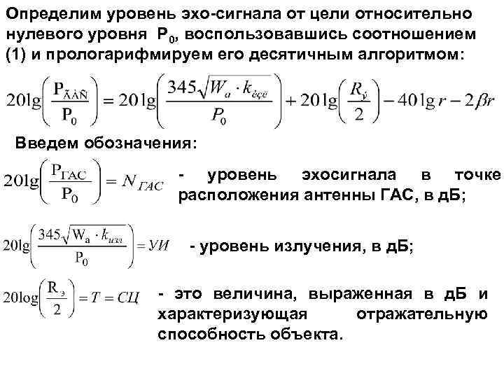 Determine the level of the echo signal from the target relative to the zero level P 0, using relation (1) and logarithm it with a decimal algorithm: Let's introduce the designations: - the level of the echo signal at the point where the GAS antenna is located, in section B; - radiation level, c. B; is a value expressed in d. B and characterizing the reflectivity of the object.
 PR is the standard propagation loss, c d. B, taking into account the attenuation of the signal during its propagation from the antenna of the GAS to the target and back, taking into account the spherical law of propagation. Taking into account the introduced designations, the expression will take the form: NGAS = UI + SC - 2 PR (2) Formula (2) is used to estimate the level of the echo signal from the target at the point of reception in a homogeneous unlimited environment without taking into account interference.
 Considering the processing of the useful signal Рgas = Рc and the interference Рп in the GAS, and taking into account the recognition coefficient δ, we can write the following expression Рgas = Рc = δ Рп Equation of the energy range of the GL mode (EP): = where k is the coefficient of the axial concentration of the antenna; Δf is the frequency band (range) of the GAS receiving path, Hz; f 0 - average frequency of the range, kHz; β = 0, 036 f 03/2 [K. Hz] - coefficient of spatial attenuation, d. B / km.
 GAS ON PN Antenna GAS UI PR STS UP Purpose PR D The equation of the range of the GL (EP) mode in symbolic form can be written (taking into account the "-" sign) as: EP = - (UI + SC - UP - PO + PN) = 2 ПР ЭП = УП (noise level) =
 PO (detection threshold) = PN (directional indicator) = Active HUSs include: - GAS for measuring distance - GAS for communication - GAS for identification - GAS for mine detection - GAS for detecting torpedoes - GAS for detecting underwater swimmers and anti-sabotage GAS - GAS for illuminating ice conditions and detecting streaks - Hydroacoustic logs - GAS side-scan

 The NK hydroacoustic armament consists of: ShGAK MGK-335 "Platina" - a hydroacoustic detection, target designation and communication complex; ØGAK MGK-345 "Bronze" - hydroacoustic complex for detection, target designation and communication; ShGAK MGK-355 "Polynom" - a hydroacoustic complex for detecting submarines and issuing target designation to anti-submarine weapons; ØGAS MG-332 "Argun", GAS MG-332 T "Argun-T" - hydroacoustic detection and target designation station for anti-submarine ships; ØGAS MG-329 "Oka", GAS MG-329 M "Oka-M" - lowered hydroacoustic station; ØGAS MG-339 "Shelon" or GAS MG-339 T "Shelon-T" - Hydroacoustic station for detection, determination of coordinates, communication and identification;
 ØGAS MG-79 or GAS MG-89 "Serna" - hydroacoustic station for detecting anchor and bottom mines; ØGAS MG-7 "Bracelet" and GAS MG-737 "Amulet-3" - hydroacoustic station for detecting underwater sabotage forces and means; ØGAS MG-26 "Host" or GAS MG-45 "Backgammon" - equipment for hydroacoustic communication and identification. ØGAS KMG-12 "Kassandra" - equipment for classifying targets for hydroacoustic stations of surface ships when they work in active mode. ØGAS MG-409 S is a passive detection system for hydroacoustic buoys. ØGAS "Altyn" - equipment for measuring the vertical distribution of the speed of sound in water from a surface ship; ØGAS MI-110 KM - wake detection equipment appl.
 Rice. 1. Project 1164 missile cruiser. Project 1164 is armed with hydroacoustic armament: q SJSC MGK-335 "Platina"; q GAS MG-7 "Bracelet" - 2 sets; q GAS MG-737 "Amulet-3"; q GAS KMG-12 "Kassandra". is the following
 Rice. 2. Large anti-submarine ship of project 1155 (1155. 1) The project 1155 is armed with the following hydroacoustic armament: SJSC MGK-335 "Platina"; GAS MG-7 "Bracelet" - 2 sets; GAS "Altyn"; GAS MI-110 KM. In service with the project 1155. 1 is the following hydroacoustic armament: SJSC MGK-355 "Polynom"; GAS MG-7 "Bracelet" - 2 sets; GAS "Altyn"; GAS MI-110 KM.
 Rice. 3. Ship of project 956. Class: missile and artillery ship, subclass: destroyer. 1 rank Project 956 is armed with the following hydroacoustic armament: SJSC MGK-355 "Polynom"; GAS MG-7 "Bracelet" - 2 sets; GAS KMG-12 "Kassandra".
 Rice. 4. Missile boat of project 1241. 2 In service with project 1241. 2 is the following hydroacoustic armament: SJSC MGK-345 "Bronza"; GAS MG-45 "Backgammon";
 Rice. 5. Project 1241 torpedo boat Project 1241 is armed with the following hydroacoustic armament: SJSC MGK-345 "Bronze"; GAS MG-45 "Backgammon";
 Rice. 6. Small anti-submarine ship of project 1124 Project 1124 is armed with the following hydroacoustic weapons: GAS MG-339 "Shelon" or GAS MG-339 T "Shelon-T"; Some projects are armed with SJSC MGK-335 "Platina"; GAS MG-322 "Argun" or GAS MG-322 T "Argun-T"; GAS MG-329 "Oka" or GAS MG-329 M "Oka-M"; GAS MG-26 "Host" or GAS MG-45 "Backgammon"; GAS KMG-12 "Kassandra". GAS MG-409 S.
 Rice. 7. Basic minesweeper BTShch of project 1265 (pr. 260, 270) The project 1265 is armed with the following hydroacoustic armament: GAS MG-79 or GAS MG-89 "Serna"; GAS "Kabarga";
 Rice. 8. Project 775 large landing ship BDK Project 775 is armed with the following hydroacoustic armament: GAS MG-7 "Braslet"; GAS MG-26 "Host" or GAS MG-45 "Backgammon".
 Hydroacoustic stations "Tamir-11" (1953) GAS for surface ships of small displacement Total number of devices - 17 Mass of devices - 1000 kg Chief Designer B. N. VOVNOBOY
 Hydroacoustic stations "Hercules" (1957) GAS for surface ships of medium and large displacement Total number of instruments - 30 Mass of instruments - 5800 kg Chief Designer UMIKOV Z. N.
 Hydroacoustic stations "Mezen-2" (1963) GAS for detecting bottom mines Total number of devices Mass of devices - 12 - 2100 kg Chief designer I. I. Nizenko
 Hydroacoustic stations "Kashalot" (1963) GAS to search for sunken ships Total number of instruments - 22 Instrument mass - 4000 kg (without spare parts) Chief Designer N. A. TIMOKHOV
 Hydroacoustic complexes "Rubin" (1964) SAC for multipurpose nuclear submarines Chief designer E. I. ALADYSHKIN Total number of instruments - 56 Weight of instruments - 54747 kg
 Hydroacoustic stations "Titan-2" (1966) GAS for large anti-submarine ships Total number of devices Mass of devices - 37 - 16000 kg Chief Designer G. M. KHARAT
 Hydroacoustic stations "Argun" (1967) GAS for small anti-submarine ships Total number of devices Mass of devices - 30 - 7600 kg with spare parts Chief Designer V. P. IVANCHENKO
 Hydroacoustic stations "Serna" (1969) GAS for detecting anchor and bottom mines Total number of devices Weight of devices - 20 - 3900 kg Chief Designer G. G. LYASHENKO
 Hydroacoustic stations "BUK" (1971) GAS for research vessels Total number of instruments Instrument mass - 30 - 11,000 kg Chief Designer Zh. P. KLIMENKO
 Hydroacoustic complexes "Platina" (1972) GAK for surface ships of medium and large displacement Chief Designer LD KLIMOVITSKY Number of devices - 64 Mass of devices - 23 tons
 Hydroacoustic complexes "Polynom" (1979) GAK for NK of large displacement Chief designer V. G. SOLOVIEV Total number of instruments - 152 Mass of instruments - 72 000
 Hydroacoustic complexes "Zvezda-M 1" (1986) Digital GAK for NK medium displacement Chief designer Aleshchenko O. M. Total number of instruments - 64 Weight of instruments - 23,000 kg
 Hydroacoustic complexes "Kabarga" (1987) GAS mine detecting for sea, base and raid minesweepers Total number of devices - 42 Mass of devices - 8500 kg Chief Designer G. G. LYASHENKO
 Hydroacoustic systems "Zvezda M 1 -01" (1988) Digital SAC for surface ships of small displacement Chief designer Aleshchenko O. M. Total number of instruments - 60 Mass of instruments - 16,500 kg
 Hydroacoustic complexes "Zvezda-2" (1993) Digital SAC for large displacement NK Chief designer Borisenko N.N. Total number of instruments - 127 Weight of instruments - 77742 kg

 Prospective complexes Corvette project 12441, which provides for the installation of the state joint stock company "Zarya-2"
In the foreseeable future, submarines and anti-submarine aircraft of the Russian navy will have to receive a new type of sonar systems. According to the latest reports, by the end of the decade, the military department intends to acquire a large number of underwater surveillance equipment. Such purchases will make it possible to equip many submarines, aircraft, etc. under construction or modernization with modern means of detection.
At the end of March, on the official website of state purchases, the Ministry of Defense placed a new order concerning the further development of the material part of the Navy. According to the published information on the tender, the ministry plans to purchase 55 hydroacoustic complexes (GAK) of the MGK-335EM-03 "Mallard" family in various modifications. For the purchase of all the required products, the military department is going to spend no more than 194.6 million rubles - an average of over 5.3 million for the complex. The first complexes within the framework of a future order should be delivered this year. Completion of deliveries is scheduled for 2019.
General scheme of the MGK-335EM-05 complex
According to the published data, the armed forces intend to purchase the Mallard complexes of three modifications, which will enable them to equip submarines, anti-submarine aircraft and stationary systems. 16 Kryakva-A complexes are being purchased for the submarine forces. The same number of systems should be received by naval aviation. 23 sets of the Mallard-V version will be purchased for hydroacoustic reconnaissance stations.
Applications for the tender are accepted until April 17. Shortly thereafter, a contract will be signed for the supply of the required products, after which their production will start. As already mentioned, the military department wants to receive the first hydroacoustic complexes of the required types this year.
According to available data, the MGK-335EM-03 Kryakva hydroacoustic complex was created by the Oceanpribor concern (St. Petersburg). This complex is designed for installation on ships of small and medium displacement. It is possible to install all the necessary equipment both during the construction of ships and during repair and modernization. In the latter case, the Mallard system is a replacement for the older MGK-355MS complex. According to reports, new modifications were created on the basis of the ship complex, intended for operation on other carriers. As a result, the SACs of the Mallard family can also be used by submarines, aircraft and stationary reconnaissance systems.
Regardless of the carrier, the complexes have similar tasks and are maximally unified. Their main task is to search for submarines. Targets are detected in active mode using echolocation or in passive mode - in this case, the intrinsic noises of targets are tracked. In addition, it is possible to detect signals from other complexes operating in active mode. Also, the "Mallard" automatics are able to independently track the found target and issue target designation data to the carrier's anti-submarine defense fire control device. There is a possibility of automated classification of the detected object. Complexes MGK-335EM-03 "Mallard" have the function of hydroacoustic communication at low and high frequencies. It also provides for the use of code communication and identification.

Architecture of SJSC MGK-335EM-03
In order to improve operational characteristics, the complexes have a number of important features and functions. During the operation of the hydroacoustic complex, the level of acoustic interference is automatically monitored. Also, the automation is able to predict the expected range of the system depending on the current conditions. There are automated tools for monitoring the operation of all components of the complex and tracking their condition. Automation independently monitors the operation of the units and makes diagnostics. In case of detection of problems in the automatic mode, their localization is carried out. Operator training is available using simulated targets.
In the basic configuration, intended for installation on surface ships, the MGK-335EM-03 "Mallard" SJC includes several main instruments that solve various problems. In this case, the main and only means of observing and detecting targets is a subtle active-passive antenna. It is made in the form of a cylindrical body equipped with a large number of sensitive elements. To maintain the required position of the antenna during operation, a special suspension system with stabilization devices is used. The antenna has a height of 1 m and a diameter of 1 m. Around the circumference of the cylinder there are 36 posts with 12 elements on each.
Also, on board the carrier ship, a generator device, a receiving-amplifying and matching device, as well as devices for digital signal processing and control and management of stabilization. All these elements of the complex are interconnected. Electricity is supplied to all components of the complex using a separate power supply device connected to general ship electrical systems.
At the operator's workplace of the complex, it is proposed to mount a console with all the necessary controls. Data on the underwater situation, detected targets and the operation of hydroacoustic equipment are displayed on two color monitors. The main controls are the keyboard and trackball located on the front console. Some of the buttons and switches are placed next to the monitors. The developer of the Mallard system also proposes the use of an external indicator. At some distance from the main console, an additional monitor can be installed that displays information about the current situation.

Duck antenna "Mallard"
According to available data, the Mallard family includes hydroacoustic systems of several models, differing from each other in the composition of special equipment, primarily antennas and other detection means. So, in the MGK-335EM-01 project, the keel antenna is supplemented by a towed flexible extended antenna. The MGK-335EM-02 complex includes a towed emitting and flexible extended antenna. The MGK-335EM-04 product is distinguished by an extended frequency range when operating in active mode, which makes it possible to detect torpedoes, and the Mallard version of the MGK-335EM-05 has a sinking receiving and transmitting antenna.
According to the official data of the Okeanpribor concern, the MGK-335EM-03 Mallard is capable of detecting a submarine with an equivalent radius of Re = 10 m at distances of up to 10-12 km. Target coordinates are determined with an accuracy of 30 'by bearing. Range accuracy reaches 1% of the distance scale. In the noise direction finding mode, the complex is capable of capturing sounds with a frequency of 1.5 to 7 kHz. After detecting the target and taking it for tracking, the bearing determination accuracy is 30 '. The hydroacoustic signal detection mode, which implies the detection of alien SACs operating in an active mode, allows you to control the frequency range of 1.5-7 kHz. The bearing to the source of the detected signal is determined with an accuracy of 10 °.
By analyzing the nature of the received reflected or intercepted signals, the MGK-335EM-03 complex is able to determine the belonging of the detected object to one or another class of equipment. With some help from the operator, the sonar system is able to distinguish a submarine from a torpedo. At the same time, it is possible to simultaneously issue target designation to anti-submarine weapons systems.
Complex "Mallard" is distinguished by rather high characteristics of hydroacoustic communication, and also has some special capabilities. Low-frequency or high-frequency communication is carried out at ranges of up to 20 km. Code communication, identification of a detected object or changing the distance to it can be performed at distances of up to 30 km. With the help of GAK MGK-335EM-03, the crew of the carrier ship can maintain telephone communication with both Russian submarines and ships using the NATO frequency range.

Complex control panel
According to the latter, in 2017-19, the navy will have to receive 55 sets of the MGK-335EM-03 "Mallard" SACs in different configurations, designed for mounting on carriers of various classes. Most of this equipment is planned to be installed at hydroacoustic reconnaissance stations, while other complexes will be used by submarines and aircraft. Accurate information about the future carriers of the ordered complexes, for obvious reasons, on this moment absent. So far, all that remains is to make forecasts and try to predict what kind of equipment will be equipped with such equipment.
In the case of anti-submarine aviation, the Il-38 and Tu-142 aircraft of the latest modifications can be considered as possible carriers of the new type of complexes. Now this technique is undergoing repairs and modernization, during which it receives various new equipment. In the next project for the renewal of equipment, the latest hydroacoustic systems can also be used.
16 complexes in the configuration for submarines will be purchased. Probably, this equipment will be used in the future repair of existing ships of relatively old projects. Considering the age and equipment of the submarines in service, it can be assumed that any domestic nuclear and diesel-electric submarines of all existing projects can become potential carriers of the Mallard systems. Not all ships of the Russian submarine forces are equipped with modern means of monitoring the underwater situation, which is why they need new similar products. As the repair progresses, they will be able to receive new devices with improved characteristics.
It is curious that in the current tender there is no clause on the purchase of hydroacoustic systems intended for installation on surface ships. The MGK-335EM-03 product was originally developed precisely as a shipborne observation device and only then developed, as a result of which it could be installed on other carriers. For some not entirely understandable reasons, the military department's immediate plans do not include the purchase of ship-based SJSC "Mallard".

Scheme of the ship complex MGK-335EM-05 with an additional drop antenna
According to domestic funds mass media, it is already known where the purchased sonar systems will go. The resulting products will be distributed by the Ministry of Defense among several formations of the navy and naval aviation, responsible for the implementation of anti-submarine defense. The equipment will go to Kronstadt, Severomorsk and Novorossiysk, as well as to some bases in the Primorsky Territory. Other details of the future operation of promising systems have not yet been reported.
From the available data it follows that equipping submarines, aircraft and stationary sonar systems with new complexes of the MGK-335EM-03 Mallard family will have positive consequences for the entire anti-submarine defense of the fleet as a whole. During the construction or modernization of submarines, aircraft, etc. will receive modern equipment for tracking underwater objects, which will accordingly affect the efficiency of their work. As a result, the range and probability of detecting potentially dangerous objects will noticeably increase.
In addition to the main tasks associated with the detection and tracking of various objects, the new SACs can be used to identify found targets, issue target designation to control systems, etc. A training regime is also provided to facilitate the training of hydroacoustic operators.
According to official data, in mid-April, the military department will finish accepting applications for the recently launched tender and will begin to select a supplier of the required equipment. Soon a supply agreement should appear, after which the serial production of the SJSC of the required modifications will begin. The first samples of such equipment are planned to be received this year, the last - no later than the end of 2019. Obviously, the supply of such products will be carried out simultaneously with the construction / modernization of their carriers. This means that no later than the beginning of the next decade, the domestic anti-submarine defense will receive new equipment, and with it new capabilities. All this will have a positive effect on the potential of the navy as a whole.
Based on materials from sites:
http://zakupki.gov.ru/
http://i-mash.ru/
http://oceanpribor.ru/
http://armsdata.net/
http://flot.com/
Soviet diesel-electric submarines of post-war construction Gagin Vladimir Vladimirovich
SUBMARINE HYDROACOUSTIC COMPLEXES IN ANTI-WATER FIGHT
Diesel-electric boats of the first post-war projects "paved the way" for the crews of modern submarines, gaining experience in operating military equipment on ocean voyages, mastering the techniques of ice navigation, studying the hydrological and hydrographic situation of strategically important areas of the ocean, practicing the tactics of anti-submarine search and anti-ship warfare.
Anti-submarine warfare tactics often boil down to the search and detection of enemy submarines using hydroacoustic means before the enemy does it.
In this case, the state of the environment surrounding the submarine is of paramount importance, especially such parameters as the zone of acoustic convergence and the position of the submarine relative to the "thermocline".
Convergence zones are ring-shaped areas around the submarine. Sound traveling downward from the convergence point located in the convergence zone refracts depending on the pressure and temperature of the water, moves up and down in relation to the surface in a spiral at irregular intervals, which also depend on the state of the environment surrounding the PL.
The commander of the ship, trying not to get into these areas - in relation to where, in his opinion, the target is, can evade detection. To do this, he needs to be within those areas where the sound propagates from its source simply radially.
The easiest way is to take a position above or below the temperature jump layer (thermocline) so that it separates the submarines - then the sounds made by its engine will most likely be reflected from the layer and the enemy boat will not detect it.
The temperature jump is the boundary layer of the underwater space separating warm surface waters and colder deeper areas.
Diesel submarines, along with nuclear ones, occupy a prominent place in the aggressive plans of the leadership of the naval forces of the NATO bloc countries. According to the Jane Handbook, there were 186 diesel boats in the Alliance's navies in mid-1980.
Diesel submarines have certain advantages over nuclear submarines. They include, in particular, less noise, which improves the operating conditions of hydroacoustic stations (GAS) when solving anti-submarine warfare problems.
At the present time, as the foreign press reports, there has been an outlined integration of hydroacoustic technology with BIUS and weapon control systems, taking place on the basis of the widespread use of computers. As a result, the tactical capabilities of hydroacoustic equipment have qualitatively changed. The likelihood of detecting targets and classifying the resulting contact has increased. In addition, it has become real to simultaneously monitor several (up to six) targets and quickly identify changes in their maneuvering, automatically receive information and continuously issue it to all associated systems and clearly, in a form convenient for direct use, display on screens and scoreboards, and register if necessary.
Digital signal processing allowed the passive location systems of the submarine to accurately determine the bearing and distance to it only by the noise of the target.
Finally, the integration of various computer-based systems simplified the control over the operation and maintenance of the GAS and made it possible to reduce the maintenance personnel, which is of no small importance for diesel submarines of relatively small displacement.
The main path of the acoustic station is the direction-finding one with a range of several tens of kilometers. In the low-frequency (220 Hz - 7 kHz) range, signals are received to a conformal (combined with the contours of the bow of the hull) acoustic antenna consisting of piezoceramic hydrophones, and in the high-frequency (8 kHz) range - to a cylindrical antenna with lead zirconate hydrophones located near the keel ... The cylindrical antenna also serves to track multiple (up to four) targets. Both noise direction finding channels complement each other. The surrounding area is surveyed by rapidly sequencing a large number of 360 ° transmitting statically shaped directional lobes. The detected noisy targets are direction finding with high accuracy using the equal signal method.
The active path made it possible to conduct a circular survey with omnidirectional radiation of one message or when a series of messages were emitted in successively changing directions, as well as emit single messages in a certain direction. The received echoes are displayed on the indicator screen and can be recorded to measure the Doppler frequency shift.
The passive location path has three receiving antennas on each side of the submarine, installed flush with the hull in the bow, middle and aft parts. They receive the target noise, which is subjected to correlation processing, which makes it possible with sufficient accuracy to determine the location of the target along three lines of position. The path antennas can be used as additional ones for the direction finding path.
The station provides directional and non-directional sound underwater communication.
The sonar signal detection path allows detecting impulse signals of various origins at a distance of several tens of kilometers, determining their frequency, duration and direction to the signal source.
Integrated circuits are widely used in the design of the station, due to which its dimensions and weight are reduced, and reliability is increased. Target data are displayed on two screens, and are automatically fed to the auto-plotter of the computer of the torpedo firing control system, where commands for firing are generated.
A simpler hydroacoustic station has also been developed. It includes paths for noise direction finding, echo direction finding and passive location. The search and detection of targets is carried out in the noise direction finding mode using the correlation method of signal processing. After detecting a target, the distance to it is measured by emitting a directed single burst or by the passive location method.
In order to increase the efficiency of the use of hydroacoustic surveillance equipment, submarines also have instruments for measuring the speed of sound propagation in water and for signaling the onset of cavitation of propellers, instruments for monitoring the level of their own noise.
To increase the efficiency of using the HAS, there is a device for constructing ray patterns based on the input data on the actual distribution of the speed of sound propagation with increasing depth. The system is capable of functioning in a simulator mode with imitation of signals arriving at its input from various targets. All current information entered into the system in the course of its combat work and generated by it can be recorded for subsequent playback and analysis. The system is served by one or two operators.
Other types of GAS have sectional cylindrical antennas. For a circular view of space, 96 radiation pattern lobes are statically formed.
Determining the coordinates of detected targets and simultaneously tracking several is carried out in all modes using a computer. In the active mode, to obtain the maximum range of action, the radiation parameters (emitted power, frequency, type of modulation of the message) are coordinated with the actual hydrological conditions in the observation area.
In the mode of detecting signals from sonars, the bearing to the signal source, its frequency and amplitude, pulse duration, pulse repetition rate are determined, and radiation sources are classified according to the totality of all these signs.
The station can also operate in auxiliary modes: simulator, beam graph and automatic control of technical condition, which ensures the detection of faulty modules.
The GAS console contains all controls and two screens. One of them with a three-color indication, which is an all-round view indicator, simultaneously displays in the central part the complete situation with its ship in the center and a circular bearing scale, and along the edges - full text information about tracked targets (distance, bearing, Doppler frequency shifts , courses, speed), data on the course and speed of your ship, on the mode and parameters of the GAS operation. The second screen displays textual hierarchical matrices, the processing of which allows you to optimize the equipment control process. This presentation of information greatly simplifies the maintenance and operation of the station and allows one operator to do it.
In November 1983, the VICTOR-III class nuclear submarine was tasked with removing the noise and other characteristics of the fourth American Ohio-class missile carrier.
According to the crew, a young, ambitious captain of our submarine, inspired by the examples of heroes submariners Patriotic War, decided to almost go into the bay of the foe's base.
For acoustic camouflage K-324 in the Sargasso Sea dived under a small boat following a suitable course. Everything was going well, when suddenly the speed of our submarine began to drop rapidly, despite the increase in turbine speed to the maximum.
No tricks and guesses of the crew led to positive results - the speed dropped to three knots.
There was nothing to be done - I had to emerge. To emerge almost in view of the American shores, in the "den" itself, so to speak.
To inspect the main propeller, the bow tanks were filled, the boat got a decent trim on the bow and the emergency team, armed with two Kalashnikovs and two PMs (the entire arsenal of the Soviet nuclear submarine), examined the stern. Indeed, some kind of cable was wound on the shaft, very strong, not amenable to either scrap or automatic fires: all efforts were in vain.
The commander decided to go to Cuba on the surface. It was then that she was captured by American pilots, sailors and tourists on pleasure yachts.
With grief in half crawled to Cuba. The commander was immediately summoned to the "carpet". But, contrary to the sad assumptions about his fate, the captain returned "on horseback" - the unfortunate cable, wound on a propeller by a desperate submariner, turned out to be nothing more than the latest American hydroacoustic antenna, which was tested on a nondescript boat by careless Americans.
Our scientists and technologists have received invaluable materials for studying ...

Emergency submarine K-324 in the Sargasso Sea
From the book Battle for the Stars-2. Cosmic Confrontation (Part II) the author Pervushin Anton IvanovichCombat orbital complexes for Buran We remember that the Energia-Buran rocket and space complex was created by order of the Ministry of Defense to solve military problems in near space. It is clear that payloads for
From the book Quality Management the author Shevchuk Denis Alexandrovich1.2. Quality management as a factor in the success of an enterprise in the competitive struggle The market economy as one of the most important characteristics includes competition between the subjects and objects of the market. Competition refers to the rivalry between individuals or
From the book Warships of the World at the Turn of XX - XXI Centuries Part III Frigates the author Apalkov Yuri ValentinovichAIRCRAFT MISSION SYSTEMS PRODUCED IN THE USA COMPOSITION AND MAIN PERFORMANCE CHARACTERISTICS "STANDARD * SM-1" STANDARD "SM-2 MK 57 NATO" SEA SPARROW "" SEA CHAPPAREL "Country Developer USA General Dinamics Corporation, Air Defense Division USA General Dinamics Corporation, Air Defense Division USA. NATO Raytheon Electronic Systems, Hughes Missile Systems Company USA Lockheed Martin Aeronutronic Year
From the book Soviet diesel-electric submarines of post-war construction the author Gagin Vladimir VladimirovichANTI-WATER MISSION COMPLEXES COMPOSITION AND MAIN PERFORMANCE CHARACTERISTICS "SWEEPER" "RASTRUB-B" "WATERFALL" "MEDVEDKA" ASROC CY-1 MILAS Country Developer Russia "Raduga" Russia "Novator" Russia "Marine engineering" USA Lockheed Systems Defense Martin China CMTIEC France GIE Milas Year of adoption on
From the book Domestic missile weapons the author Pervov, Mikhail AndreevichSOME ASPECTS OF ANTI-SUBMERSIBLE FIGHT The submarine forces underwent fundamental qualitative changes after the Second World War. Submarines have evolved from diving into true submarines, autonomy, diving depth, speed and range
From the book Domestic anti-tank complexes the author Angelsky Rostislav DmitrievichR-101R -101 (R-102) LAND-AIR SAMPLES R-101R -101 Experimental anti-aircraft guided missile. Equipped with rocket engine. Developed in the second half of the 40s. at NII-88 on the basis of the German captured Wasserfall anti-aircraft missile. Tests took place in 1948. Chief Designer - Eugene
From the book Secret Cars of the Soviet Army the author Kochnev Evgeny DmitrievichV-753 "VOLKHOV" M-2 MARINE AIRCRAFT MISSION SYSTEMS. В-753 (13DM) Experienced sea surface-to-air missile system M-2 with a two-stage guided missile equipped with a sustainer LPRE and a starting solid propellant rocket. Created on the basis of the S-75 land-based air defense system. Complex developer - CDB
From the book Aviation in Local Wars author Babich V.K."Igla" PORTABLE ANTI-MISSION SYSTEMS (photo from "Military Parade" magazine) "Strela-2" "Strela-2M" "STRELA-2" 9K32. 9M32 The 9K32 portable anti-aircraft missile system with a solid-propellant small-sized guided missile. The first domestic portable air defense system. Intended
From the book Electronic homemade products author Kashkarov A.P.ANTI-MISSION COMPLEXES A. V-1000 Experimental (range) anti-missile defense system "A" with the anti-missile V-1000. The first domestic missile defense system. It was deployed at the Sary-Shagan training ground. Provided the defeat of one medium-range monoblock ballistic missile.
From the book Metal of the Age the author Nikolaev Grigory IlyichANTITANK COMPLEXES OF THE SECOND GENERATION "Fagot" The anti-tank complex "Malyutka", which was put into service in 1963, basically met the requirements of the troops and subsequently proved to be an effective weapon in the course of local wars. However, and
From the book Evolution of anti-submarine systems of domestic ships author Karjakin LeonidANTI-TANK MISSION COMPLEXES OF THE NINETY
From the author's bookMobile missile and artillery systems The first Br-264 launcher for mounting on a car chassis was created at the Barrikady plant design bureau in September 1961 and was part of the experimental OTRK 9K71 Temp with the 9M71 solid-propellant rocket, which was developed with
From the author's book3. In the struggle for survival In local wars, as noted, the survival rate was assessed by foreign experts in terms of the level of losses - the ratio of the number of aircraft downed to the number of sorties made. For example, the level of losses of a tactical squadron,
From the author's book4.8.2. Effective Anti-Noise Techniques When dealing with power line noise, it is best to use a combination of RF line filters and suppressors. transient processes in line alternating current... This method can achieve 60 dB interference attenuation at frequencies up to
From the author's bookChapter 1. IN THE FIGHT AGAINST THE CORROSION OF THE BEACH OF METALS There is nothing eternal in the world - everyone has known this simple truth for a long time. What seems to be forever unshakable - mountains, granite blocks, whole continents - eventually collapse, crumble into dust, go under water, sink into the depths.
From the author's bookANTI-SUBMARINE MISSION COMPLEXES As already mentioned, with the advent of nuclear submarines in the 1950s, new weapons systems were required that could engage submarine targets at long range. In the USSR, work in this direction was started in accordance with
Russian underwater hydroacoustics at the turn of the 21st century
Military hydroacoustics is an elite science, the development of which can only be afforded by a strong state
German ALEXANDROV
Possessing the highest scientific and technical potential (the company employs 13 doctors and more than 60 candidates of sciences), the concern develops the following priority areas of domestic hydroacoustics:
Multifunctional passive and active sonar systems (GAS) and systems (GAS) for illuminating the underwater environment in the ocean, including for submarines, surface ships, aircraft, detection systems for underwater swimmers;
Systems with flexible extended towed antennas for operation in a wide frequency range for surface ships and submarines, as well as stationary;
Active, passive and active-passive stationary hydroacoustic systems to protect the shelf zone from unauthorized entry by surface ships and submarines;
Hydroacoustic navigation and search and survey systems ";
Hydroacoustic transducers, antennas, phased antenna arrays of complex shapes with up to several thousand receiving channels;
Acoustic screens and sound-transparent fairings;
Information transmission systems via hydroacoustic channel;
adaptive systems for processing hydroacoustic information in a complex hydroacoustic and signal-jamming environment;
Target classifiers by their signatures and by the fine structure of the sound field;
Sound speed meters for surface ships and submarines.
The concern today is ten enterprises located in St. Petersburg and the Leningrad Region, Taganrog, Volgograd, Severodvinsk, the Republic of Karelia, including research institutes, factories for the serial production of hydroacoustic equipment, specialized enterprises for servicing equipment at facilities, training grounds. These are five thousand highly qualified specialists - engineers, workers, scientists, more than 25% of whom are young people.
The company's team has developed almost all serially produced SJSC pl (Rubin, Ocean, Rubicon, Skat, Skat-BDRM, Skat-3), a number of sonar systems and systems for surface ships (Platina "," Polynom ", station for detection of underwater swimmers" Pallada "), stationary systems" Liman "," Volkhov "," Agam "," Dniester ".
The hydroacoustic complexes for submarines created by the enterprise are unique technical means, the creation of which requires the highest knowledge and vast experience in hydroacoustics. As one wit said, the task of detecting a submarine with a noise-direction finder is similar in complexity to the task of detecting a candle flame at a distance of several kilometers on a bright sunny day, and nevertheless, for a submarine in a submerged position, the SAC is practically the only source of information about the environment. ... The main tasks solved by the submarine sonar complex are the detection of submarines, surface ships, torpedoes in the noise direction finding mode, automatic tracking of targets, determining their coordinates, target classification, target detection and direction finding in sonar mode, intercepting sonar signals in a wide frequency range, providing sound underwater communications at long distances, providing an overview of the near situation and the safety of navigation, lighting the ice situation when sailing under the ice, providing mine and torpedo protection of the ship, solving navigation problems - measuring the speed, depth of the place, etc. In addition to these tasks, the complex must have a powerful automated control system, a system for monitoring its own noise, must continuously perform the most complex hydrological calculations to ensure the functioning of all systems and to predict the situation in the area of operations of the submarine. The complex has simulators for all systems of the hydroacoustic complex, which provide education and training of personnel.
The basis of any hydroacoustic complex is antennas, phased discrete arrays of complex shapes, consisting of piezoceramic transducers, which must ensure the reception of signals from the water environment on a boat, experiencing enormous loads due to hydrostatic pressure. The task of the SAC is to detect these signals against the background of its own noise, flow noise when the boat is moving, sea noises interfering with targets, and also a host of factors masking the useful signal.
A modern SAC is a complex digital complex that processes huge streams of information in real time (each antenna of the complex consists of thousands, or even tens of thousands individual elements, each of which must be processed in sync with all others). Its operation is possible only when using the latest multiprocessor systems that provide the task of simultaneous, in space, and multiband, in frequency, observation of the surrounding acoustic fields.
The most important and most critical element of the complex is the devices for displaying the information received. When creating these devices, not only scientific and technical, but also ergonomic, psychological problems are solved - it is not enough to receive a signal from the external environment; the safety of the ship, and the movement of many targets, surface, underwater, air, representing potential threat or interest for a submarine. And the developers are constantly balancing on the brink of the problem - on the one hand, to display the maximum amount of information processed by the complex and necessary for the operator, on the other hand, not to violate the Miller rule limiting the amount of information that can be mastered simultaneously by a person.
An important feature of hydroacoustic systems, especially antennas, is the requirements for their strength, durability, and the ability to work without repair or replacement for a very long time - as a rule, it is impossible to repair a sonar antenna in combat service.
A modern SAC cannot be considered as a self-sufficient, closed system, but only as an element of an integrated surveillance system, which receives and uses continuously updated a priori information about targets from non-acoustic detection systems, reconnaissance, etc., and outputs information about the changing underwater environment to the system , which analyzes tactical situations and makes recommendations on the use of various modes of the SAC in this situation.
The development of sonar systems for a submarine is a continuous competition with the developers of a potential enemy, on the one hand, since the most important task of the SAC is to ensure at least parity in a duel situation (the enemy hears and recognizes you, and you him at the same distance), and it is necessary by all means and means to increase the range of the SAC, and mainly in a passive noise direction finding mode, which allows you to detect targets without revealing your own location, and with shipbuilders, submarine designers, on the other, since the noise of submarines decreases with each new generation, with each new project , even with each new ship built, and it is necessary to detect a signal at a level lower by orders of magnitude than the surrounding noise of the sea. And it is obvious that the creation of a modern hydroacoustic complex for submarines of the XXI century is a joint work of the developers of the complex and the developers of the boat, jointly designing and placing the elements of the SAC on the ship in such a way that its work under these conditions is most effective.
The experience in the design of SJSC pl, available at our institute, allows us to highlight the main problem areas from which we can expect a significant increase in efficiency in the near future.
1. SAC with conformal and conformal cover antenna
The decrease in the noise level of the square, associated with the efforts of the designers to optimize the technical solutions for the structures of its hull and mechanisms, led to a noticeable decrease in the range of the SJSC on modern square. The increase in the aperture of traditional antennas (spherical or cylindrical) is limited by the geometry of the nose end of the housing. An obvious solution in this situation was the creation of a conformal (combined with the contours of the pl) antenna, the total area, and hence the energy potential of which significantly exceeds the analogous indicators for traditional antennas. The first experience in creating such antennas turned out to be quite successful.
An even more promising direction is the creation of conformal-integumentary antennas located along the side of the square. The length of such antennas can be tens of meters, and the area is more than a hundred square meters. The creation of such systems is associated with the need to resolve a number of technical problems.
The conformal-sheath antenna is located in the area of the predominant influence of inhomogeneous waves caused by structural interference, as well as interference of hydrodynamic origin, including that arising due to the excitation of the body by the incident flow. Acoustic screens, traditionally used to reduce the effect of interference on the antenna, are not effective enough in the low-frequency range of onboard antennas. Possible ways of providing effective work on-board antennas, judging by foreign experience, are, firstly, the constructive placement of the most noisy machines and mechanisms of the sub so that their effect on the on-board systems is minimal, and secondly, the use of algorithmic methods to reduce the effect of structural interference on the GAK tract ( adaptive methods for compensating for structural interference, including the use of vibration sensors located in the immediate vicinity of the antenna). The use of the so-called "vector-phase" methods of information processing seems to be very promising, which make it possible to increase the efficiency of the complex operation due to the joint processing of pressure and vibrational velocity fields. Another way to reduce the influence of hydrodynamic interference affecting the efficiency of conformal-sheath antennas is the use of film transducers (PVDF plates), which, due to averaging over an area of 1.0x0.5 m, significantly (judging by the data in the literature - up to 20 dB) the influence of hydrodynamic interference on the GAK tract.
2. Adaptive algorithms for processing hydroacoustic information, consistent with the propagation medium
“Adaptation” is traditionally understood as the ability of a system to change its parameters depending on changes in environmental conditions in order to maintain its efficiency. As applied to processing algorithms, the term "adaptation" means the alignment (in space and time) of the processing path with the characteristics of signals and interference. Adaptive algorithms are widely used in modern complexes, and their efficiency is determined mainly by the hardware resources of the complex. More modern are algorithms that take into account the space-time variability of the signal propagation channel. The use of such algorithms makes it possible to simultaneously solve the problems of detection, target designation and classification, using a priori information about the signal propagation channel. The source of such information can be adaptive dynamic oceanological models predicting with sufficient reliability the distributions of temperature, density, salinity and some other parameters of the environment in the area of action of Sq. Such models exist and are widely used abroad. The use of sufficiently reliable estimates of the parameters of the propagation channel allows, judging by the theoretical estimates, to significantly increase the accuracy of determining the coordinates of the target.
3. acoustic systems placed on guided unmanned underwater vehicles, solving the tasks of polystatic detection in active mode, as well as the tasks of searching for silted bottom objects
The submarine itself is a huge structure, more than a hundred meters long, and far from all the tasks the solution of which is necessary to ensure its own safety can be solved by placing hydroacoustic systems on the ship itself. One of these tasks is the detection of bottom and silted objects that pose a danger to the ship. To view an object, you need to approach it as close as possible, without creating threats to your own safety. One of the possible ways to solve this problem is to create a controlled underwater unmanned vehicle, placed on a submarine, capable, independently or by control via wire or sonar communication, to approach the object of interest and classify it, and, if necessary, destroy it. In fact, the task is similar to the creation of the hydroacoustic complex itself, but miniature, having a battery propulsion unit, located on a small self-propelled device capable of undocking from a submarine in a submerged state, and then docking back, while providing constant two-way communication. In the United States, such devices have been created and are included in the armament of the latest generation submarines (of the Virginia class).
4. Development and creation of new materials for hydroacoustic transducers, which are less weight and cost
The piezoceramic transducers that make up submarine antennas are extremely complex designs, piezoelectric ceramics itself is a very fragile material, and it takes considerable effort to make it strong while maintaining efficiency. And for a long time there has been a search for a material that has the same properties of converting vibration energy into electrical energy, but which is a polymer, durable, lightweight, and technological.
Technological efforts abroad have led to the creation of polymer films of the PVDF type, which have a piezoelectric effect and are convenient for use in the design of cover antennas (placed on board a boat). The problem here is primarily in the technology of creating thick films that provide sufficient antenna efficiency. Even more promising seems to be the idea of creating a material that has the properties of piezoelectric ceramics, on the one hand, and the properties of a protective shield that muffles (or scatters) the enemy's sonar signals and reduces the ship's own noises. Such material (piezoresin), applied to the submarine's hull, actually makes the entire hull of the ship a sonar antenna, providing a significant increase in the efficiency of sonar means. An analysis of foreign publications shows that in the United States, such developments have already entered the stage of prototypes, while in our country in recent decades there has been no progress in this direction.
5. Classification of goals
The problem of classification in hydroacoustics is the most difficult problem associated with the need to determine the target class based on information obtained in the direction finding mode (to a lesser extent, according to the active mode data). At first glance, the problem is easily solved - it is enough to register the spectrum of a noisy object, compare it with the database, and get an answer - what kind of object it is, with an accuracy down to the name of the commander. In fact, the spectrum of the target depends on the speed of movement, the angle of the target, the spectrum observed by the hydroacoustic complex contains distortions caused by the passage of the signal through a randomly inhomogeneous propagation channel (aquatic environment), which means it depends on the distance, weather, area of action and many other reasons that make the problem of spectrum recognition practically insoluble. Therefore, in the domestic classification, other approaches are used related to the analysis of characteristic features inherent in a particular class of goals. Another problem requiring serious scientific research, but urgently needed, is the classification of bottom and silted objects associated with the recognition of mines. It is known and confirmed experimentally that dolphins quite confidently recognize air- and water-filled objects made of metal, plastic, wood. The researchers' task is to develop methods and algorithms that implement the same procedure that a dolphin performs when solving a similar problem.
6. The task of self-defense
Self-defense is a complex task of ensuring the safety of a ship (including anti-torpedo protection), including detection, classification, target designation, and the issuance of initial data for the use of weapons and (or) technical means of countermeasures. The peculiarity of this task is the integrated use of data from various subsystems of the SAC, identification of data coming from various sources, and ensuring information interaction with other ship systems that ensure the use of weapons.
The above is only a small part of those promising areas of research that need to be addressed in order to increase the effectiveness of the hydroacoustic weapons being created. But from an idea to a product is a long way, requiring advanced technologies, a modern research and experimental base, a developed infrastructure for the production of the necessary materials for hydroacoustic transducers and antennas, etc. It should be noted that recent years have been characterized for our enterprise by a serious technical re-equipment of the production and testing base, which became possible thanks to funding within the framework of a number of federal target programs, both civil and special purpose, conducted by the Ministry of Industry and Trade. Russian Federation... Thanks to this financial support, over the past five years, it was possible to completely repair and significantly modernize the largest hydroacoustic experimental pool in Europe, located on the territory of Okeanpribor Concern OJSC, to radically update the production capacities of the serial factories that are part of the concern, thanks to which the Priboy Taganrog plant became the most advanced instrument-making enterprise in the south of Russia. We are creating new productions - piezo materials, printed circuit boards, in the future - the construction of new production and scientific areas, stands for setting up and commissioning of equipment. In 2 - 3 years, the production and scientific capacities of the enterprise, backed up by the "data bank" of new ideas and developments, will make it possible to start creating the fifth generation hydroacoustic weapons, which are so necessary for the Navy.