 entrance
Homemade television antenna: for DVB and analog signal - theory, types, manufacture. Manufacturing antenna for digital TV with their own hands Broadband antenna do it yourself
It is not always appropriate to buy a good antenna for the cottage. Especially if it is visited from time to time. The point is not so much in costs, how much is that it may not be in place after a while. Therefore, many prefer to make an antenna for cottages on their own. The cost is minimal, the quality is not bad. And most important moment - the antenna TV can be made in half an hour and then, if necessary, it is easily repeated ...
Digital television in the DVB-T2 format is transmitted in the DMW range, and there is no digital signal, or it is not. If the signal is accepted, the picture is a good quality. Concerning. For reception digital television Any decimeter antenna is suitable. Many radio amateurs are familiar to Telastanin, which is called "zigzag" or "eight". This TV antenna is collected with their own hands literally in minutes.
To reduce the number of interference from the back of the antenna put a reflector. The distance between the antenna and the reflector is selected experimentally - according to the "purity" pictures  You can attach foil on the glass and get a good signal ....
  Copper tube or wire - optimal option, well bend, easy
It is very simple to do it, the material is any conductive metal: tube, rod, wire, strip, corner. She takes, despite the simplicity, good. It looks like two squares (rhombus) interconnected. In the original, the reflector is located per square - for more confident reception of the signal. But it is more needed for analog signals. To receive digital television, you can easily do without it or then if the reception will be too weak.
Materials
Optimally, a copper or aluminum wire with a diameter of 2-5 mm is suitable for this homemade teleconnenna. In this case, you can do everything literally in an hour. You can also use a tube, a corner, a band of copper or aluminum, but it will be necessary to be some kind of device to extend the framework of the desired form. Wire can be bent with a hammer, consolidating it in the vice.

The coaxial antenna cable of the required length will also be required, the plug is suitable for the connector on your TV, some fastening for the antenna itself. The cable can be taken with the resistance of 75 ohms and 50 ohms (the second option is worse). If there is a TV antenna with your own hands for installation on the street, pay attention to the quality of insulation.
The mount depends on where you are going to hang a homemade antenna for digital television. On the upper floors you can try to use it as home and hang on the curtains. Then the large pins are needed. In the country or if you take homemade teleconnen on the roof, it will be necessary to mount it to the sixth. For this occasion, look for suitable fixators. To work, you will also need a soldering iron, sandpaper and / or file, feet.
Does the calculation need
To receive a digital signal there is no need to consider the wavelength. It is just desirable to make an antenna more broadband - to take as many signals as possible. To do this, some changes are made to the original design (in the photo above) (further in the text).
If you wish, you can make a calculation. To do this, you need to know what the wave the signal is broadcast, divided into 4 and get the desired side of the square. To get the required distance between the two parts of the antenna, make the outdoor side of the rhombuses slightly longer, internal - shorter.

Drawing antenna "Eight" for receiving digital TV
- The length of the "inner" side of the rectangle (B2) - 13 cm,
- "Outdoor" (B1) - 14 cm.
Due to the difference of the length, the distance between the squares is formed (they should not connect). Two extreme plots are made longer than 1 cm - so that you can turn the loop to which the coaxial antenna cable is soldered.
Frame manufacturing
If you calculate all the lengths, it will turn out 112 cm. Cut off the wire or the material that you have, we take the passatology and a ruler, begin to bend. Corners must be at 90 ° or so. With the lengths of the parties, you can make a little wrong - this is not fatal. It turns out:
- The first section is 13 cm + 1 cm on the loop. The loop can be bent immediately.
- Two sections of 14 cm.
- Two 13 cm, but with a turn in the opposite direction - this is the place of inflection on the second square.
- Two 14 cm again.
- The latter is 13 cm + 1 cm on the loop.
The actual antenna frame is ready. If everything was done correctly, between two half in the middle it turned out a distance of 1.5-2 cm. There may be small discrepancies. Next, the loops and the location of the inflection are cleaned up to a pure metal (to handle emery with small grain), to fill. Two loops to connect, enhance the passage to keep tight.

Cable preparation
We take an antenna cable, carefully cleaned. How to do this is shown on a step-by-step photo. Clean the cable is needed on both sides. One edge will be attached to the antenna. Here we clean so that the wire is sticking out for 2 cm. If it turned out more, too much (then) can be cut off. Screen (foil) and braid twisted in the harness. It turned out two conductors. One is central cable monashed, the second - twisted from a variety of braid wiring. Both are needed and they must be fed.

To the second edge, we swell the plug. There is enough length of 1 cm or so. Also form two conductors, fill.
The plug in those places where we will carry out the soldering, wipe with alcohol or solvent, clean the essay (you can nadfil). To put on the plastic part of the plug on the cable, you can now start a soldering. To the central revenue of the plug, we solder mono-coat, to the side - stranded twist. Last - enhance the capture around isolation.

Then you can simply turn the plastic tip, in can be poured with glue or a tok-cutting sealant (this is important). While the glue / sealant is not frozen, we quickly collect the plug (screw the plastic part), we remove the excess composition. So the plug will be almost eternal.
DVB-T2 TV antenna do it yourself: assembly
Now it remains to connect the cable and frame. Since we did not bind to a specific channel, we will fasten the cable to the midpoint. This will increase the broadband of the antenna - there will be more channels. Therefore, the second divided end of the cable solder to the two sides in the middle (those that cleaned and Ludili). Another difference from the "original version" - the cable is not necessary to circle on the frame and fall at the bottom. This will also expand the reception range.
The collected antenna can be checked. If the reception is normal, you can finish the assembly - pour the place of soldering sealant. If the reception is bad, try to start finding a place where it is best. If there are no positive changes, you can try to replace the cable. For ease of experiment, you can use the usual phone noodle. She is worth a penny. It is soldered to her plug and frame. Try with her. If "catches" is better - it's a bad cable. In principle, you can work on "noodle", but not long - it will quickly come into disrepair. Better, of course, put a normal antenna cable.

To protect the place of connecting the cable and the frame of the antenna from atmospheric influences, the place of the soldering can be cooled by the usual tape. But this is a way unreliable. If you don't forget, you can put out several shrink tubes before soldering, so that with their help to be insulated. But most reliable way - Pour everything with glue or sealant (they should not carry out the current). As a "hull", it is possible to use covers for 5-6 liter cylinders with water, ordinary plastic roofs per cans, etc. In the right places, we make a deepening - the frame "smallele" in them, do not forget about the cable output. Fill the sealing composition, we wait until it grab. All, the TV antenna do it yourself for receiving digital television is ready.
Homemade Antenna Double and Triple Square
This is a narrowband antenna that is used if you need a weak signal. It can even help if a weaker signal is "clogged" more powerful. The only drawback is needed an accurate orientation to the source. The same design can be done to take digital television.
 You can make five frames - for more confident reception
  Painting or varnishing undesirable - the reception is worse. This is possible only in close proximity to the transmitter
The advantages of this design - the reception will be confident even at a considerable distance from the repeater. It will only be necessary to specifically find out the broadcast frequency, withstand the size of the framework and the matching device.
Design and materials
Make it from tubes or wire:
- 1-5 TV Channel MV range - tube (copper, brass, aluminum) with a diameter of 10-20 mm;
- 6-12 TV Channel MV range - tubes (copper, brass, aluminum) 8-15 mm;
- DMB range - copper or brass wire with a diameter of 3-6 mm.
The antenna is a double square represents two frames connected by two arrows - top and bottom. Little frame - vibrator, large - reflector. Antenna consisting of three frames gives a greater gain. The third, smallest, square called the director.

The top arrow connects the middle of the frames, can be made of metal. Lower - from insulating material (textolite, ghettium, wooden plank). The frames should be installed so that their centers (dials of the crossing of diagonals) were on one straight line. And this direct should be sent to the transmitter.
Active frame - Vibrator - has an open circuit. Its ends are screwed to the textolite plate of 30 * 60 mm. If the frames are made from the tube, the edges are flattened, nor do the holes and the lower arrow is fixed through them.
Mast for this antenna should be wooden. In any case, the upper part of it. Moreover, the wooden part should begin at a distance of at least 1.5 meters from the level of the antenna framework.
Dimensions
All sizes for the manufacture of this antenna TV are provided with their own hands in the tables. The first table is for a meter range, the second is for decimeter.

In three-frame antennas, the distance between the ends of the vibrator (medium) frames make more - 50 mm. The remaining sizes are given in the tables.

Connecting an active frame (vibrator) through a short-circuit loop
Since the frame is a symmetric device, and it is necessary to connect it to an asymmetrical coaxial antenna cable, you must match the device. In this case, the symmetric short-circuited loop is usually used. It is made of segments of antenna cable. The right segment is called "Clay", the left - "feeder". The cable, which goes to the TV is attached to the place of connection of the feeder and the plume. The length of the segments is selected based on the wavelength of the received signal (see the table).

A short segment of the wire (loop) is separated from one end, removing the aluminum screen and twisting the braid into a dense harness. His central conductor You can cut to isolation, as it does not play values. Seal and feeder. Here, too, remove the aluminum screen and twisted the braid into the harness, but the central conductor remains.
Further assembly happens like this:
- The brace of the loop and the central feeder conductor are soldered to the left end of the active frame (vibrator).
- Fider's braid solder to the right end of the vibrator.
- The lower end of the loop (braid) is connected to the feeder braid with a rigid metal jumper (you can use the wire, just ensure good contact with the braid). In addition to electrical connection, it still sets the distance between the sections of the matching device. Instead of a metal jumper, you can be tied to the harness of the bottom of the loop of the lower part of the loop (remove the insulation on this site, delete the screen, fold in the harness). To provide good contact The harnesses are soldered with each other.
- Cable pieces must be parallel. The distance between them is about 50 mm (some deviations are possible). Fixators from dielectric material are used to fix the distance. You can also attach the matching device to the textolite plate, for example.
- The cable that goes to the TV is soldered to the bottom of the feeder. The braid is connected to the braid, the central conductor with the central conductor. To reduce the number of connections, the feeder and cable to the TV can be made uniform. Only in the place where the feeder must end. It is necessary to remove the isolation so that the jumper can be installed.
This matching device allows you to get rid of the interference, a vague contour, the second blurred image. Especially it is commemorated at a large distance from the transmitter when the signal will be clogged with interference.
Another version of the triple square
In order not to connect a short-circuit loop, the triple square antenna vibrator is elongated. In this case, you can connect the cable directly to the frame as shown in the figure. Only the height on which the antenna wire sold is determined in each case individually. After assembly, the antenna is carried out "tests". Connect the cable to the TV, the central conductor and the braid move up / down, achieving best image. In that position, where the picture will be the clearer, solder outlets of an antenna cable, the place of the soldering isolate. The position can be any - from the bottom jumper, to the location of the transition to the frame.

Sometimes one antenna does not give the desired effect. The signal is obtained by a weak image - black and white. In this case, the standard solution is to install a television signal amplifier.
The most simple antenna for giving - from metal cans
For the manufacture of this television antenna, except the cable, there will be only two aluminum or tin cans and a piece of a wooden plank or a plastic pipe. Banks must be metallic. You can take beer aluminum, can be tin. The main condition is that the walls are even (not ribbed).

Banks are washed and dried. The end of the coaxial wire is divided - twisting braids and clearing the central core of isolation receive two conductors. They are fixed to banks. If you can, you can solder. No - take two small self-press with flat hats (you can "fleece" for drywall), at the ends of the conductors twist the loop, they have merged with a screw from the washer installed on it, screw to the bank. Just before this it is necessary to clean the metal banks - removing the flare with the help of sandpaper with thin grain.

Banks are fixed on the bar. The distance between them is selected individually - at the best picture. You should not hope for a miracle - in normal quality there will be one or two channels, and maybe there is no ... depends on the position of the repeater, the "purity" of the corridor, how correctly the antenna is oriented ... But as an emergency entry is a great option.
Simple antenna for Wi-Fi from metal cans
Antenna for reception wi-Fi signal You can also make from the remedies - from tin can. This TV antenna can be collected for half an hour. This is if everything is slow. The bank must be made of metal, with even walls. Great and narrow cans are excellent. If you put a homemade antenna on the street, find the jar with a plastic lid (as in the photo). The cable take an antenna, coaxial, resistance of 75 ohm.

In addition to banks and cables, it will be necessary:
- rF-N radio frequency connector;
- a piece of copper or brass wire with a diameter of 2 mm and a length of 40 mm;
- cable with a socket suitable for a Wi-Fi map or adapter.
Wi-Fi transmitters operate at a frequency of 2.4 GHz with a long wave of 124 mm. So, it is desirable to choose the bank to choose such that its height is at least 3/4 wavelengths. For a given case, it is better that it be more than 93 mm. The diameter of the jar should be as close as possible to half the wavelength - 62 mm for this channel. Some deviations can be, but the closer to the ideal - the better.
Sizes and assembly
When assembling a jar make a hole. It must be positioned strictly at the desired point. Then the signal will enhance several times. It depends on the diameter of the selected jar. All parameters are shown in the table. Measure exactly the diameter of your jar, find the desired line, have all the desired dimensions.

| D - diameter | Lower border of attenuation | Upper border of attenuation | LG | 1/4 LG. | 3/4 LG. |
|---|---|---|---|---|---|
| 73 mm | 2407.236 | 3144.522 | 752.281 | 188.070 | 564.211 |
| 74 mm | 2374.706 | 3102.028 | 534.688 | 133.672 | 401.016 |
| 75 mm | 2343.043 | 3060.668 | 440.231 | 110.057 | 330.173 |
| 76 mm | 2312.214 | 3020.396 | 384.708 | 96.177 | 288.531 |
| 77 mm | 2282.185 | 2981.170 | 347.276 | 86.819 | 260.457 |
| 78 mm | 2252.926 | 2942.950 | 319.958 | 79.989 | 239.968 |
| 79 mm | 2224.408 | 2905.697 | 298.955 | 74.738 | 224.216 |
| 80 mm | 2196.603 | 2869.376 | 282.204 | 070.551 | 211.653 |
| 81 mm | 2169.485 | 2833.952 | 268.471 | 67.117 | 201.353 |
| 82 mm | 2143.027 | 2799.391 | 256.972 | 64.243 | 192.729 |
| 83 mm | 2117.208 | 2765.664 | 247.178 | 61.794 | 185.383 |
| 84 mm | 2092.003 | 2732.739 | 238.719 | 59.679 | 179.039 |
| 85 mm | 2067.391 | 2700.589 | 231.329 | 57.832 | 173.497 |
| 86 mm | 2043.352 | 2669.187 | 224.810 | 56.202 | 168.607 |
| 87 mm | 2019.865 | 2638.507 | 219.010 | 54.752 | 164.258 |
| 88 mm | 1996.912 | 2608.524 | 213.813 | 53.453 | 160.360 |
| 89 mm | 1974.475 | 2579.214 | 209.126 | 52.281 | 156.845 |
| 90 mm | 1952.536 | 2550.556 | 204.876 | 51.219 | 153.657 |
| 91 mm | 1931.080 | 2522.528 | 201.002 | 50.250 | 150.751 |
| 92 mm | 1910.090 | 2495.110 | 197.456 | 49.364 | 148.092 |
| 93 mm | 1889.551 | 2468.280 | 194.196 | 48.549 | 145.647 |
| 94 mm | 1869.449 | 2442.022 | 191.188 | 47.797 | 143.391 |
| 95 mm | 1849.771 | 2416.317 | 188.405 | 47.101 | 141.304 |
| 96 mm | 1830.502 | 2391.147 | 185.821 | 46.455 | 139.365 |
| 97 mm | 1811.631 | 2366.496 | 183.415 | 45.853 | 137.561 |
| 98 mm | 1793.145 | 2342.348 | 181.169 | 45.292 | 135.877 |
| 99 mm | 1775.033 | 2318.688 | 179.068 | 44.767 | 134.301 |
The procedure for such:

You can do without RF connector, but everything is much easier with it - it is easier to set the emitter vertically up, connect the cable to the router (router) or Wi-Fi map.
To date, to broadcast television signals began to be applied digital standard DVB-T. For receiving gear on analog TVs You can make an antenna for digital TV with your own hands, which is connected to a special converting signal to the console.
[Hide]
Requirements for digital batch television antenna
To ensure the reception of the signal and transfer it to the antenna amplifier must comply with the following requirements:
- Customizing elements should be located along the axis of waves coming from the transmitter.
- Have protection against interference with a close frequency to the television signal. Other radio signals, gaskets from running electrical engines and generators can be interference.
- The design of the antenna must minimize the power loss of the signal during transmission.
- The antenna scheme should be based on the type of polarization.
Types of television antennas
Antennas for receiving a television signal are divided into several types that differ in frequencies of received signals.
Distribution received the following types:
- Version Antenna, which can receive a digital and analog signal. The reception distance of analog signals is not large and does not exceed the range of the direct visibility of the television tower.
- The logopeodic antenna capable of receiving the waves of the meter and decimeter range.
- Decimeter antenna designed to receive short waves only.
The author of the Dmitry video will tell about the manufacture of a simple antenna for digital TV.
How to find out the source data for calculating the antenna
The key parameter on which the quality of the digital signal is depends is the radiation wavelength. Based on this length, selected dimensions Usov antenna. To determine the wavelength, the calculation of the formula λ \u003d 300 / F is applied, where F is equal to the frequency of the transmitted signal in MHz. This parameter is in open access and can be easily installed through any Internet search engine.
Make from a cardboard box
The simplest variant of the home antenna, which can be quickly made from the remedies itself, is a device based on a cardboard shoe box.
For manufacture, you will need:
- food aluminum foil;
- cut of a standard coaxial cable;
- malyary or Stationery Scotch;
- tube quick-drying glue, for example, rubber "moment".
The manufacture of antenna looks like this:
- Cut foil on the bottom of the box. Grease the box with glue and stick foil, uniformly smoothing it along the bottom.
- Cut two pieces of a coaxial cable with a length of 500 mm.
- Remove the insulation of the cable shielding from each end to a distance of no more than 25 mm.
- Shift the screen and twist it into a separate core.
- Bend each segment on the shape of a circle.
- Secure with the help of a tape segment on the outer part of the box cover in the form of the number 8. The ends of the cable must be directed towards the G8 and are located at least 10 mm from each other.
- At a length of about 100 mm, deteriorate the outer insulation of the cable, which will bind the antenna with the receiver.
- Twist the screen into a separate core.
- Gradually remove the insulation of the central conductor until a section of a bare wire with a length of about 95-100 mm will be obtained.
- Pierce the bottom of the box with the foil and enter the cable inside.
- Remove the wire through the lid and spend it along the contour of one of the parts of the "eight" to the central part. Secure the cable.
- Connect together three braid veins. Then copp the three output of the central wire. Reconfigure the knot to scotch.
- Install the plug at the reverse end of the coaxial cable.
- Locate the antenna in the place of the best reception, which is determined by the experimental way.
If everything is done correctly, the antenna will allow the main channels of television in DVB T2 format. The photo below shows the main stages of the manufacture of antenna.
Casting bottom Foil  Laying rings on the lid
  Submission of the main cable
  Connection of conductors
How to make an overwhelming antenna
Those who want to save on the purchase can make an antenna for receiving a digital signal independently by selecting one of the designs described below.
From coaxial cable
The simplest design of the antenna can be considered a piece of a coaxial cable with a length of 2-3 m, which has a plug at one end. The free end is cleaned from the outer layer of isolation, the screen is woven into a separate conductor and is assigned to the side. Then the insulation of the central wire is cut along a small piece. After that, the wire is located on the window or windowsill, selecting the appropriate place by experimental path.
It should be noted that such a design is operational only at a distance of confident reception, where the Singal is quite powerful. With a large removal from the repeater or location of the receiver in the zone of the dense building, it is necessary to apply other antennas designs.
Of the two petals
This version of the television antenna is made from a pair of small metal plates having a form of an equally chained triangle, and two wooden or plastic rivers. A copper wire with a diameter of 2-4 mm is stretched between these elements.
Scheme of petal antenna
The fastening step on the rails is 25-30 mm. Triangular bases are combined with a soldering at a distance of 10 mm from each other, the wire is also soldered to triangles. To connect to the television receiver applied coaxial cable RK75. The wire screen is connected on the rail (location indicated by a yellow point), and the central wire is to the place of the connection of triangles. In the zones of bad reception, the antenna is recommended to use together with the amplifier.
Butterfly
For more sustainable signal reception essential television An antenna of the "Butterfly" type is used. Homemade device This design can be used at home and in the country. It will provide good reception quality only with a stable broadcast signal.
To make the reception device, you will need materials and tools from the list:
- the board with a length of at least 600 mm and the width of about 70 mm, the thickness can be any, but preferably 15-20 mm;
- single-core copper wire with a conduit diameter of at least 4 mm;
- self-tapping screws or metal and washers;
- coaxial cable RK75;
- antenna plug connector;
- roulette;
- boxes;
- screwdriver with crushing sting;
- wire stripping knife;
- soldering iron with a capacity of 40-60 W;
- solder and flux for soldering.
The antenna for digital TV is collected as follows:
- Perform the markup of the board, which will serve as an antenna frame, in accordance with the schematic drawing below. The distance between the vertical rows of the holes is 25 mm. The holes are located at the same distance from the edges of the board.
- Cut the wire for 8 segments of 375 mm and two - 220 mm.
- Remove isolation from the central part of each long segment on a plot of about 25 mm.
- Bend cables in the shape of the letter V with the same segments. The distance between the ends should be 75 mm.
- Install V-shaped segments on a blackboard using screws. For dense fixation under the head of the screws, pucks should be placed.
- Before tightening self-tapping screws, mount additional short connectors. On short wires, it is necessary to remove insulation on the field of contact with V-shaped conductions.
- Connect a coaxial cable to the lower row of self-tapping. The installation scheme is shown below.
Antenna from cans with a protective case
How to make a logoeriodic antenna
For the manufacture of the framework of such a device are used:
- aluminum P-shaped profile with the height of the side of about 15 mm;
- antenna's mustache applies studs with a suitable diameter and length or smooth tubes and rods;
- a small segment of an aluminum tube with a diameter of 10-15 mm, which is used as a support.
The sequence of manufacturing the simplest antenna looks like this:
- Slide the tube from two ends and bend it in the form of the letter U. One unpacked end should be attached to the P-shaped profile using self-samples.
- Make a pair of the Usa antenna with a length of 70, 85, 100, 120, 140 and 170 mm. Cut on one side of the thread.
- Drill in a P-shaped opening profile for installing a mustache. The distances between the holes are indicated in the diagram.
- Screw to each mustache, set the assembled part into the opening of the P-shaped profile.
- Fasten the mustache inside the profile with nuts. For each nut to put a connecting terminal, which can be factory manufacture or homemade from a copper conductor.
- Swing the yield outputs in a certain sequence (given in the diagram).
Ring Antenna Scheme: 1 - Ring, 2 - Extra Loop, 3 - Main Cable
In the form of a frame
Another option is a framework design, called the antenna HARCHENKO, made of thick copper wire with a diameter of 30-4 mm.
Antenna assembly looks like this:
- Cut wire 112 cm long.
- Clean and irrigate the ends of the wire that will be bent into the loop.
- To bend it in the form of two rectangles in the following sequence - 10 mm fixation loop, then an edge of 130 mm long, then two ribs of 140 mm, two - at 130, two - at 140, the last edge has a length of 130 mm and ends the loop to which The last 10mm wire leaves.
- Connect the loop at the ends and suck the joint.
- Dilute this angle from the opposite of 20 mm (shown in the photo below). Wire a wire located opposite the junction of the loops.
- Clean the coaxial cable by 20 mm for the screen and 10 mm - for the central vein.
- Fit conclusions to irradiated corners on the frame.
- Make a central housing from a plastic cover of a suitable size.
- To put the square frames with the cable and fuel the bulk. After soaring glue, install the antenna in the place of the best signal reception.
To calculate the parameters of the Harchenko antenna, there are specialized online calculators that calculate all product data.
Amplifier based on the MAX2633 scheme
For the manufacture of the amplifier, three capacitors with a capacity of 1 NF and resistance with a nominal value of 1 kΩ are required. To power such a device, a constant voltage is used from 3 to 5 V. The device does not require configuration, but the degree of amplification is adjusted by setting the resistance of another nominal value (to reduce the degree of amplification it is necessary to increase resistance). Such an amplifier is not broadband and applicable only for short-wave range.
For broadband gain when receiving a signal at long distances, transistor devices are used, schemes which are shown below.
 Amplifier based on the general emitter of the transistor Kt368
  Amplifier at the common base of the CT315 transistor
  Chestransistor amplifier
In the process of self-assembly of such devices, it is necessary to make printed circuit boards With tracks. When using wires for connecting elements, the amount of interference increases, which will reduce the gain coefficient.
For an amplifier based on KT368, resistance and capacitors will be needed with the following parameters:
- 100 ohms (R1 and R4);
- 470 Ohm (R2);
- 51 com (R3);
- 1000 PF (C1);
- 33 PF (C2);
- 15 PF (C4 and C3).
The assembled amplifier is installed as close as possible to the receiver and can be used for antenna of any type. It does not need to configure and works from the source. direct current with a voltage of 9 V.
Amplifiers built on a common transistor base are used to expand the frequency range. These devices also do not need additional adjustment of the parameters of the work.
In the assembly process, components will be required:
- 51 ohms (R1);
- 10 com (R2);
- 15 com (R3);
- 1 com (R4);
- capacitors have the same nominal as in a circuit with a common emitter.
In the amplifier diagram, a throttle coil is used, which is wound from 300 turns of the wire of 0.1 mm (type PEV) on the ferrite ring.
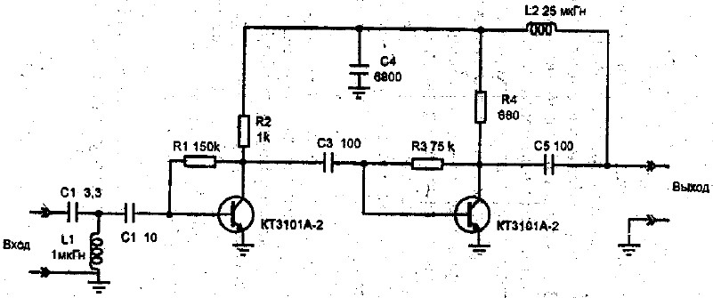
In the case of a completely weak signal, it is possible to use multi-stage schemes operating from direct current with a voltage of 12 V and constructed on two GT311D transistors.
In the amplifier scheme for the antennas of a long-range action, used:
- 680 ohms (R1);
- 75 com (R2);
- 1 com (R3);
- 150 com (R4);
- 100 PF (C1, C2, C4);
- 6800 PF (C3);
- 15 PF (C5);
- 3.3 PF (C6);
- 100 μH (L1);
- 25 μH (L2);
- homemade throttle of 25 turns of the wire PEV2 with a diameter of 0.8 mm (L3).
Despite the rapid development of the Internet, television remains the main source of information for the majority of the population. But in order for your TV to have a high-quality picture, you need good antenna. It is not necessary to buy a television antenna in the store, because it can be made with your own hands and save decent money at the same time.
How to make high-quality antennas for various ranges of broadcasting and what materials to use, you can find out our article.
There are many types and forms of television antennas, below are the main of them:

- Antennas for the reception of the "Wave Channel".

- Antennas receiving "running wave".

- Frame antennas.

- Zigzag antennas.

- Logoperiodic antennas.
 Rate antennas
 - Rate antennas.
Antennas for receiving digital television
The whole world, including our country, switched from analog broadcast to digital. Therefore, making an antenna with your own hands or buying it in the store, you need to know which antenna is better suitable for receiving the DVB-T2 format:

- Room antenna - Suitable for receiving a signal in DVB-T2 format only at a distance of up to 10 kilometers from the repeater. In principle, at this distance, the signal is capable of adopting even the usual bare wire inserted into the antenna connector of the TV and directed to the desired side, but for a more stable and stable signal, it is better to use the room antenna.

- Voron Antenna - It is capable of receiving a digital signal at a distance of 30 kilometers. This type of antenna is installed outside the dwelling and does not require a clear focus on the repeater. But in cases where the distance from the source of the signal is more than 30 kilometers or there are no interference generators, it is advisable to direct the antenna to the TV.

- Dipol 19 / 21-69 Antenna - takes a signal at a distance of 50 kilometers. Requires an installation on an elevation of 8-10 meters and a clear direction to the source of the signal. In a bundle with an amplifier, it is capable of receiving a digital signal at a distance of 80-100 kilometers. Excellent characteristics this antenna make it one of better options For receiving a signal in DVB-T2 format at a remote distance from the repeater.
If you live not far from the computer, you can easily make the simplest antenna for receiving a signal in the DVB-T2 format with your own hands:
- Measure 15 centimeters of an antenna cable from the connector.
- Remove from the cropped edge of 13 centimeters of external insulation and patch, leave only a copper rod.
- Check on the picture of the TV, set the rod in the right direction.
All antenna is ready! It should be noted that such a primitive antenna is not capable of providing a high-quality and stable signal on a distance remote from the computer and in places with interference sources.
Antennas do it yourself
Let's consider several options for television antennas that can be made independently, from the primary materials:
Basket Antenna
Antenna from beer cans can be made literally for half an hour, from your hand. Of course, a super-stable signal such an antenna will not provide, but for temporary use in the country or in the removable apartment it is quite good.
 Basket Antenna
 To make the antenna you will need:
- Two aluminum cans from under beer or other drink.
- Meters five television cable.
- Plug.
- Two screws.
- Wooden or plastic base on which banks will be attached (many use a wooden hanger or mops).
- Knife, pliers, screwdriver, insulating tape.
Making sure that all of the above items are available, make the following:
- Clean one end of the cable and attach the plug to it.
- Take the second end of the cable and remove the isolation from it with a length of 10 centimeters.
- Break down the fever and twist it into the cord.
- Remove the plastic layer is an insulating cable rod for a distance of one centimeter.
- Take the banks and turn screws in the center or cover in them.
- Attach the rod to one bank, and to another cord string cable, twisting them on screws.
- Attach the banks on the base with the help of the tape.
- Fasten the cable on the base.
- Insert the plug into the TV.
- Navigating the room, determine the place of the best signal reception and secure there an antenna.
There are other variations of this antenna, with four and even eight banks, but the explicit effect of the number of cans on the quality of the signal is not detected.
How to make an antenna from beer cans you can also learn from the video:
Zigzag antenna Kharchenko
The antenna received its name in 1961, by the last name of its inventor Kharchenko K. P., who suggested using the telecast antenna of a zigzag form for reception. This antenna is very well suited for receiving a digital signal.
 Antenna Kharchenko
 For the manufacture of a zigzag antenna you will need:
- Copper wire with a diameter of 3-5 mm.
- Television cable 3-5 meters.
- Solder.
- Soldering iron.
- Plug.
- Insulating tape.
- A piece of plastic or plywood for the base.
- Bolts of fixtures.
First you need to make an antenna frame. To do this, we take the wire and and cut off a piece of 109 centimeters. Next, bend the wire so that we have a frame of two parallel rhombuses, each side of the rhombus should be 13.5 centimeters, from the remaining centimeter, make a loop for fastening the wire. Using the soldering iron and solder, connect the ends of the wire and close the frame.
Take the cable and clean it up in such a way that you can have the ability to solder the rod and the cable screen to the frame. Next, solder the rod and the cable screen in the center of the frame. Note that the screen and the rod should not touch.
Install the frame on the base. The distance between the corners of the frame in the connection site with the cable must be two centimeters. Base size Make about 10 by 10 centimeters.
Clean the second end of the cable and install the plug.
If you need to attach the antenna base to the rack, for further installation on the roof.
More detailed instructions For the manufacture of antenna Kharchenko, you can see the video:
Coaxial cable antenna
For the manufacture of antenna, you will need a 75-ohm coaxial cable of a standard connector. To calculate the cable length of the cable, you need to know the frequency of digital broadcasting and divide it in megahertz to 7500, and the resulting amount is rounded.
 Antenna from cable
 After receiving the cable length, do the following:
- Clean the cable on one side and insert the antenna in the connector.
- Return two centimeters from the edge of the connector and make a mark from which you will measure the length of the antenna.
- Measuring the desired length, bite the extra pliers.
- In the area of \u200b\u200bthe mark, remove the insulation and the cable fever, leave only internal isolation.
- Generate the purified part at an angle of 90 degrees.
- Adjust the TV set with a new antenna.
Visually consolidate the information you can watch the video:
Satellite antenna
It is necessary to immediately make a reservation that the tuner and special console are required for the reception of the satellite signal. Therefore, if you do not have this equipment, the creation of a satellite antenna will not be possible, because you can make only a parabolic reflector:

- Parabola from Orctecla - manufactured by heating. The plexiglass is placed on a disc repellent form of a parabolic reflector and is placed in a high temperature chamber. After softening the plexiglass, it takes the shape of the blank. After cooling the plexiglass, it is pulled out of the form and glue foil. The minus of this production of the homemade parabola is that the cost of its manufacture, exceed the market value of the factory reflector.
- Metal sheet reflector - Made from a sheet of galvanized iron, the size of the meter per meter. The sheet is attached to the round shape and cuts are made from the edge of the petals to the center. After that, the sheet is placed on the curved pattern of the reflector and the "petals" are fasten with point welding or ripples.
- Mesh reflector - Made from the frame and grid. First, the parameters of which are calculated by the formula. The template makes radial parabolas from copper wire. Wire section is selected based on the diameter of the antenna. For example, for an antenna with a diameter of 1.5 meters, a wire with a diameter of 4-5 mm is taken. It is also necessary to make circular belts. The diameter of the belts changes in 10-30 cm increments. After the framework of the frame, it is tightened with a fine copper grid.
All of the above methods can be considered seriously from sports interest, since the manufacture of a parabolic reflector into manual, the process is very laborious and expensive. In addition, to produce accurate calculations of the parameters of the satellite antenna at home, it is very difficult. So we advise you not to originate and buy satellite antenna In full set.
Antenna amplifier
If in place where you live a weak television signal and the usual antenna cannot provide a high-quality picture in your TV, then the antenna amplifier can help in this situation. Make it with your own hands, you can if you understand a little in electronics and know how to solder. 
Amplifiers need to be installed as close as possible to the antenna. The power amplifier is better to carry out the coaxial cable through the junction.
 Diagram of power junction
 The junction is set at the bottom of the TV and on it from the adapter is powered by 12 volts. Double-stage amplifiers consume no more than 50 milliamperes, for this reason the power of the power supply should not exceed 10 watts.
All connections of the antenna amplifier on the mast must be performed using a soldering, since the installation of mechanical compounds will lead to corrosion and rupture, with further operation in conditions of an aggressive external environment.
There are cases when you have to receive and enhance a weak signal in the presence of powerful signals from other sources. In this case, weak and strong signals fall at the inlet input. This leads to blocking the operation of the amplifier or the translation of it into a nonlinear mode that blends both signals, which is expressed in the applix image from one channel to another. Repair the situation will help reduce the supply voltage of the amplifier.
Note that the decimamer amplifiers are very strongly affected by the signals in the meter range. To attenuate the impact of meter signals, the PMW amplifier put the upper frequency filter, which blocks meter waves and skips the signals of only the decimeter range.
Below is a diagram of an antenna amplifier of the meter range:
 Scheme of the antenna amplifier of the meter range
 - The gain is 25 dB. at a voltage of 12.6 volts.
- Current current no more than 20 milliam.
- The counter-parallel inclusion of diodes D1 and D2 protects the transistor from failure when lightning strikes.
- Cascades have a common emitter.
- The C6 condenser provides the correction of the constant characterization of the amplifier in the field of high frequencies.
- To stabilize the transistor mode, the amplifier covers negative feedback With the emitter of the second transistor on the basis of the first.
- In order to avoid self-excitation of the amplifier, an unleashing filter R4 C1 is used.
We also offer to familiarize yourself with the decimeter amplifier scheme:
 Scheme of decimeter amplifier
 - Antenna amplifier of the decimeter range of 470-790 megahertz.
- Repair ratio of 30 dB. at a voltage of 12 volts.
- Current consumption 12 milliammeter.
- Cascades have a common emitter and microwave transistors with a low level of own noise.
- Resistors R1 and R3 provide temperature compensation of transistors.
- The power amplifier is powered by a coaxial cable.
With the principle of the antenna amplifier, you can read the video:
Now, having familiarized with the schemes and armed with a soldering iron, you can safely start making an antenna amplifier.
We hope that our article about television antennas turned out to be useful for you!
In the country areas, the television signal is rarely taken without amplification: too far from the repeater, the relief is usually heterogeneous, and the trees interfere. For the normal quality of "pictures", you need antennas .To, who at least a little to handle a soldering iron, can make an antenna for giving with your own hands. Aesthetics outside the city is not like that of great importance, the main - quality of reception, simple design, low cost and reliability. You can experiment and do yourself.
Simple television antenna
If the repeater is within 30 km from your cottage, you can make the most simple on the design part. These are two identical tubes interconnected by cable. The cable output is fed to the appropriate television input.
The design of the antenna for the TV in the country: do it yourself very simple (to increase the size of the picture, click on it with left mouse button)
What is needed for the manufacture of this TV antenna
First of all, you need to know at what frequency the nearest television is broadcast. The frequency depends the length of the "Usov". The broadcast band is in the range of 50-230 MHz. It is divided into 12 channels. For each needed its length tubes. The list of channels of essential television, their frequencies and the parameters of the television antenna for self-making will lead in the table.
| Canal number | Channel Frequency | Length of the vibrator - from one to the other end of the tubes, see | Length of cables for a matching device, L1 / L2 cm |
|---|---|---|---|
| 1 | 50 MHz | 271-276 cm | 286 cm / 95 cm |
| 2 | 59.25 MHz | 229-234 cm | 242 cm / 80 cm |
| 3 | 77.25 MHz | 177-179 cm | 187 cm / 62 cm |
| 4 | 85.25 MHz | 162-163 cm | 170 cm / 57 cm |
| 5 | 93.25 MHz | 147-150 cm | 166 cm / 52 cm |
| 6 | 175,25 MHz | 85 cm | 84 cm / 28 cm |
| 7 | 183.25 MHz | 80 cm | 80 cm / 27 cm |
| 8 | 191.25 MHz | 77 cm | 77 cm / 26 cm |
| 9 | 199.25 MHz | 75 cm | 74 cm / 25 cm |
| 10 | 207.25 MHz | 71 cm | 71 cm / 24 cm |
| 11 | 215.25 MHz | 69 cm | 68 cm / 23 cm |
| 12 | 223.25 MHz | 66 cm | 66 cm / 22 cm |
So, in order to make an antenna for the TV with your own hands, you need the following materials:

It would be nice to have a soldering iron, a flux for soldering copper and solder: All connections of central conductors are preferably disappearing: the image quality will be better and the antenna will work longer. Places of pieces then need to be protected from oxidation: it is best to pour the silicone layer, it is possible - epoxy resin, etc. As a last resort - take it with a tape, but it is very unreliable.
This homemade antenna for the TV, even at home, will make a child. You need to cut off the tube of that length, which corresponds to the frequency of broadcasting the nearby repeater, then cut it exactly in half.
Order assembly
The resulting tubes are discussed on one side. These ends are attached to the holder - a piece of hetinaks or textolite with a thickness of 4-6 mm (see the picture). The tubes are located at a distance of 6-7 cm from each other, their long-distance ends must be on the distance specified with the table. They are fixed to the holder, they should be kept firmly.
The installed vibrator is fixed on the mast. Now you need to connect two "usa" through the matching device. This is a cable loop with a resistance of 75 ohms (type RK-1, 3, 4). Its parameters are indicated in the extreme right column of the table, and how it is done - in the right side of the photo.
The average cable veins are screwed (soldered) to the discharged ends of the tubes, their braid is connected by a piece of the same conductor. Get the wire simply: cut off a piece of slope slightly more than the desired size and free from all the shells. Ends Clean and fasten to cable wiring (better supay).
Then the central conductors are connected from two pieces of matching the loop and the cable that goes to the TV. Their braid is also connected by a copper wire.
Last Action: The loop in the middle is fixed to the rod, it is also screwed down to the cable going down. The bar is raised to the desired height and there "set up". For configuration, two people need: one turns the antenna, the second is watching TV and evaluates the picture quality. Having determined where the signal is best received, the antenna made by its own hands is fixed in this position. To do not suffer for a long time with "setup", see where the receivers of neighbors (essential antennas) are directed. The simplest antenna for giving with his own hands is made. Install and "catch" the direction by turning it along its axis.
About how to cut a coaxial cable Watch the video.
;
Pipe loop
This antenna for giving with your own hands is slightly harder in the manufacture: you need pipe bender, but the radius of reception is more - up to 40 km. The source materials are practically the same: metal tube, cable and rod.
The radius of the bend pipe is notable. It is necessary that the pipe has the desired length, and the distance between the ends was 65-70 mm. Both "wings" should be the same long, and the ends should be symmetrical about the center.

Homemade TV antenna: a television receiver with a radius of receiving up to 40 km from a piece of pipe and cable (to increase image sizes, click on the left key of the mouse)
The length of the pipe and cable is indicated in the table. Learn, at what frequency broadcasts the relay closest to you, choose the appropriate string. Screw the pipe of the desired size (diameter is desirable 12-18 mm, the parameters of the matching loop are given).
| Canal number | Channel Frequency | Length of the vibrator - from one to the other end, see | Length of the cable for a matching device, see |
|---|---|---|---|
| 1 | 50 MHz | 276 cm | 190 cm |
| 2 | 59.25 MHz | 234 cm | 160 cm |
| 3 | 77.25 MHz | 178 cm | 125 cm |
| 4 | 85.25 MHz | 163 cm | 113 cm |
| 5 | 93.25 MHz | 151 cm | 104 cm |
| 6 | 175,25 MHz | 81 cm | 56 cm |
| 7 | 183.25 MHz | 77 cm | 53 cm |
| 8 | 191.25 MHz | 74 cm | 51 cm |
| 9 | 199.25 MHz | 71 cm | 49 cm |
| 10 | 207.25 MHz | 69 cm | 47 cm |
| 11 | 215.25 MHz | 66 cm | 45 cm |
| 12 | 223.25 MHz | 66 cm | 44 cm |
Assembly
The tube of the required length bend, making it absolutely symmetrical relative to the center. One edge is flattened and brewed / seal. Fill the sands, and close up the second side. If there is no welding, you can drown the ends, just put the plugs on good glue or silicone.
The resulting vibrator is fixed on the mast (rod). It is screwed to the ends of the pipe, and then the central conductors of the coordination loop and the cable, which goes to the TV is puzzled. The next step is to connect a piece of copper wire without insulation of the braid cables. The assembly is completed - you can start "configuration".
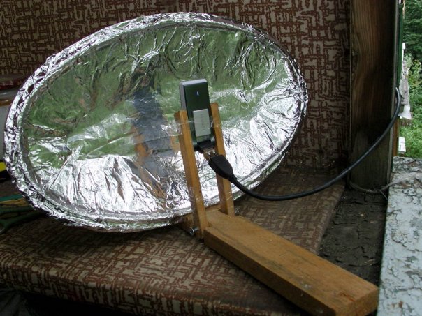
Basket Antenna
Despite the fact that it looks out seriously, the image becomes much better. Verified repeatedly. Try!
Outdoor antenna from beer cans

We collect like this:
- In the bottom of the banks strictly centered hole (5-6 mm in diameter).
- Through this hole, stretch the cable, output it through the hole in the lid.
- This bank is fixing the left on the holder so that the cable is sent to the middle.
- I pull out the cable from the bank approximately 5-6 cm, remove the insulation about 3 cm, we disassemble the braid.
- Cutting the braid, its length should be about 1.5 cm.
- It is distributed over the surface of the can and solder.
- The central conductor sticking on 3 cm must be soldered to the bottom of the second bank.
- The distance between two banks needs to be made as small as possible and fix in any way. One of the options is sticky tape or tape.
- Everything, homemade antenna DMB is ready.
The second end of the cable is finished with a suitable plug, turn on the TV jack. This design, by the way, can be used to receive digital television. Fir your TV supports this signal format (DVB T2) or there is a special console to the old TV, you can catch a signal from the nearest repeater. You only need to know where it is located and there to send your television antenna, made with your hands from tin cans.

Simple homemade antennas can be made from tin cans (from under beer or drinks). Despite the frivolousness of the "components" it works very well, and it is very simply made
The same design can be adapted to receive a meter channel channels. Instead of 0.5 liter cans, put on 1 liter. Will take MV range.
Another option: if there is no soldering iron, or you do not know how to solder, you can make it easier. Two banks are tied at a distance of several centimeters to the holder. The end of the cable is cleaned by 4-5 centimeters (carefully remove the insulation). The braid is separated, you are tied to the harness, you make a ring on it, in which the self-sustain is. From the central conductor, make the second ring and through it the second self-tapping screw. Now at the bottom of one cans we clean the speck, to which the screws are screwed.
In fact, for better contact need a soldering: braid carriage is better to post and sob, like a place of contact with metal cans. But also on self-drawing, it turns out not bad, however, the contact periodically oxidizes and it needs to be cleaned. How will "snow" you will know why ...
Antenna for digital TV do it yourself
Antenna design - frame. For this option of the receiving device you will need a crosstorn from wooden boards and a television cable. We also need a tape, several nails. Everything.
We have already said that for receiving a digital signal, only a decimeter ether antenna is needed and the corresponding decoder. It can be built into televisions (new generation) or made in the form of a hotel device. If the signal reception function in the DVB T2 code on the TV is there, connect the antenna immediately to the TV. If there is no decoder in the TV, you will need to purchase digital console And the output from the antenna is connected to it, and it is to the TV.
How to decide on the channel and calculate the perimeter of the frame
In Russia, a program was adopted, on which the towers are constantly being built. By the end of 2015, the entire territory should be covered by repeaters. On the official website http: //xn--p1aadc.xn--p1ai/when/ Find your tower nearest to you. There is a broadcast frequency and channel number. The perimeter of the antenna frame is depends on the channel number.

For example, on the 37 channel broadcasting is carried out at a frequency of 602 MHz. Long wave is considered as follows: 300/602 \u003d 50 cm. This will be the perimeter of the frame. Calculate similarly to another channel. Let it be 22 channels. Frequency 482 MHz, wavelength 300/482 \u003d 62 cm.
Since this antenna consists of two frames, then the length of the conductor should be equal to the double wavelength, plus 5 cm on the connection:
- for 37 channels, we take 105 cm of copper wire (50 cm * 2 + 5 cm \u003d 105 cm);
- for 22 channels need 129 cm (62 cm * 2 + 5 cm \u003d 129 cm).
Assembly
The copper wire is best used from the cable, which will continue to receive a receiver. That is, take the cable and remove the shell and braid from it, freeing the central conductor of the desired length. Act carefully it can not be damaged.
- for 37 channels: 50 cm / 4 \u003d 12.5 cm;
- for 22 channels: 62 cm / 4 \u003d 15.5 cm.
The distance from one nail to another must match these parameters. The laying of copper wire begins to the right, from the middle, moving down and then on all points. Only in the place where the frames are suitable close one to the other, do not shorterate the conductors. They should be at some distance (2-4 cm).

When the entire perimeter is laid, the braid from the cable long in several centimeters is twisted into the harness and solder (primed, if it does not work out) to the opposite edge of the frame. Further, the cable is laid as shown in the figure, priming it with a tape (can be more often, but the laying track cannot be changed). Then the cable goes to the decoder (separate or built-in). All antenna for giving with your own hands for accepting digital television is ready.
How to make an antenna for digital television with your own hands - another design is shown in the video.
Today, almost all houses are connected to cable or satellite televisionand almost all channels go to good quality. But what to do if you just take off the apartment? A home-made antenna for digital television will come to the rescue - as a reliable and inexpensive factory alternative. As it is done, read further.
To do specified device, It is necessary to use a phaneer 550 by 70 mm, several self-pressing, and copper forty with a centimeter wire of 40 cm long (central lived - 4 mm in diameter).
The base of the product is a plate. Share cut 8 pieces of wire, the length of which is 375 mm, while they must be cleaned in the center by 20-30 mm. This is necessary to ensure good contact in the signal transmission.
Now, cut 2 wiring, the length of which is 220 mm and relying on the size of the plank, they should be cleaned where the connections will be. After that, the remaining wiring (eight pieces), you need to begin so that they acquire the "V"-shaped form.

antenna for digital television is absolutely no different from the usual decimeter antenna.
At first, you should buy a special plug, after which they must be connected by an antenna and cable. This is quite easy. Desktop soldering iron plug is attached to the wire. Installing this cable is performed on top of the bottom connection of the device. At this stage, the production of antenna can be considered over. It is ready for inclusion.

antenna for digital television is absolutely no different from the usual decimeter.
The second method of manufacturing a digital television antenna from cans
Here, we will not use the finished device as the basis. The device will be fully assembled from the remedies. The homemade antenna for digital television is manufactured using:

- wooden trempel;
- scotch or tape;
- soldering clothes;
- two tin cans;
- several meters of wire (approximately 3-5 m);
- plugs.
To begin with, you need to refine a standard television cable. To do this, you need to cut his soft shell slightly. Under the shell, you will see the silver "foil". This material covers the cable with multiple layers. For this reason, to see the wire itself, you will need to cut around 10 cm with the edge. After that, the foil layer should be cleaned, in order to make the sample of its middle layer by about 10 mm. The reverse end of the cord is equipped with a plug used to connect to the TV.

Cable finished, on the line of cans. If we talk about the sizes, then to take a digital signal will be enough of tin tank, the volume is 750-1000 mm. The end of the wire is fastened to one bank, which with the "foil" (otherwise, the channel mapping will be incorrect). The core core cable is screwed onto the second jar. Connect the cable and banks preferably soldering. In the case of fixing the wire with a tape, most likely, the product will not work.
The only option to apply such a material is the case when the banks are installed on top of the tremble. However, and here it is impossible to retreat from the application technology. Namely, the location of the cans should form a straight line. Tin containers should be located at a distance of about 7-8 cm one from another.
That's all, a homemade antenna for digital television is ready. Now you can search for a suitable signal and securing your device. Such an antenna will allow you to view multiple channels, up to 10-15 if the signal is not pardoned.
Video: homemade antenna for digital television