 entrance
Memory for lithium ion batteries. Charging for lithium batteries screwdriver with their own hands
At this time, lithium-ion batteries are very popular, they are used in various gadgets, for example, phones, smart clock, players, lanterns, laptops. For the first time, the battery of this type (Li-Ion) released a well-known Japanese company Sony. Schematic scheme The simplest battery is presented in the picture below, having gathered it, you will have the opportunity to independently restore the charge in batteries.
Homemade Charging Lithium Akb - Electric Scheme
The basis for this instrument is two stabilizer chips 317 and 431 (). The integral stabilizer LM317 in this case serves as a current source given this part in the TO-220 housing and be installed on the heat sink using thermal paste. TL431 voltage regulator manufactured by Texas Instruments except this, in SOT-89, TO-92, SOP-8, SOT-23, SOT-25 housings and others.


LEDs (LED) D1 and D2 any, pleasant color for you. Me were chosen by such: LED1 red rectangular 2.5 mm (2.5 Milicadel) and LED2 green diffusion 3 mm (40-80 Milicadel). It is convenient to use SMD LEDs if you do not install a ready-to-housing board.

The minimum power of the resistor R2 (22 OHM) 2 watts, and R5 (11 OHM) 1 watt. All out 0.125-0.25w.

A variable resistor by 22 kiloma should be necessarily the type of SP5-2 (imported 3296w). Such variables of the resistor have a very accurate adjustment of the resistance, which can be smoothly adjusting the worm pair, similar to a bronze bolt.

Photo of the Li-Ion battery voltage measurement cell phone Before charging (3.7V) and after (4.2V), the capacity of 1100 Ma * h.
Printed circuit board for lithium charger

PCB (PCB) exists in two formats for different programs - Archive is located. Dimensions ready pCB In my case, 5 by 2.5 cm. On the sides left space for fasteners.
How charging works
How does the ready scheme work such a charger? First, the battery is charging permanent currentwhich determines the resistance of the resistor R5, with a standard nominal value of 11 ohms it will be about 100 mA. Next, when the rechargeable source of energy will have a voltage of 4.15-4.2 volts will be charged with a constant voltage. When the charging current decreases to small values, the D1 LED will stop glowing.

As is known, the standard voltage for charging Li-ion is 4.2V, this number must be installed at the output of the circuit without load, with a voltmeter, so the battery will be charged completely. If you slightly reduce the voltage, somewhere 0.05-0.10 volts, then your battery will not be charged to the end, but it will last longer. Article author EGOR.
Discuss the article charger lithium batteries
Inventions and the use of tools with autonomous power sources has become one of business cards our time. All new active ingredients that improve battery assemblies are being developed and implemented. Unfortunately, the batteries cannot work without recharging. And if on devices that have constant electrical network access, the issue is solved by embedded sources, then for powerful power sources, for example, a screwdriver, separate chargers are necessary for lithium batteries Taking into account the peculiarities different types batteries.
Recent years, products on the lithium-ion active component are increasingly used. And this is understandable, so - as these power sources have proven themselves from a very good side:
- they have no memory effect;
- almost completely eliminated self-discharge;
- can operate at minus temperatures;
- well hold discharge.
- the amount is adjusted to 700 cycles.
But, each type of batteries has its own characteristics. So, lithium - an ion component requires the design of elementary batteries with a voltage of 3, 6B, which requires some individual characteristics for such products.
Features of recovery
With all the advantages of lithium-ion batteries, they have their drawbacks - this is the possibility of internal closure of elements during charging overvoltage due to active lithium crystallization in the active component. There is also a limit on the minimum voltage value, which leads to the impossibility of receiving electrons by the active component. To exclude the consequences, the battery is equipped with an internal controller that breaks the chain of elements with the load when critical values \u200b\u200bachieve. These elements are stored Best when charging 50% at +5 - 15 ° C. Another of the features of lithium-ion batteries is that the battery life depends on its production time, regardless of whether it was in operation or not, Or in other words is subject to the "effect of aging", which limits the service life - five years.
Charging lithium - ion batteries

The simplest charging device of one element
In order to understand more sophisticated schemes Charging lithium - ion batteries, consider a simple charger For lithium batteries, more precisely for one battery.
The basis of the scheme leaves control: The TL 431 microcircuit (performs the role of an adjustable stabitron) and one transistor of the return conduction.
As can be seen from the circuit, the control electrode TL431 is included in the transistor database. The device setting comes down to the following: You need to set the voltage to the device 4.2B at the device output - this is set to the stabilion adjustment by the connection to the first leg of the resistance R4 - R3 with a nominal 2.2 com and 3 com. This chain is responsible for adjusting the output voltage, the voltage adjustment is installed only once and is stable.
Next, the charge current is adjusted, the adjustment is performed by resistance R1 (in the diagram of the face value 3) if the emitter of the transistor is turned on without resistance, then the input voltage will be on the charging terminals, that is, it is 5V, which may not comply with the requirements.
Also, in this case, the LED will not be lit, and it signals the flow of the saturation process. The resistor may be a nominal value from 3 to 8 ohms.
To quickly adjust the voltage on the load, resistance R3 can be installed adjustable (potentiometer). The voltage is adjusted without load, that is, without resistance of the element, with a par value of 4, 2 - 4.5V. After achieving the required value, it is enough to measure the amount of resistance a variable resistor And put the main detail of the desired nominal instead. If there is no necessary nominal value, it can be collected from several pieces with a parallel or serial connection.
R4 Resistance is designed to open the base of the transistor, its nominal must be 220Ω. In an increase in the battery charge, the voltage will increase, the control electrode of the transistor will increase the transition resistance to the emitter - collector, reducing the charging current.
The transistor can be used by KT819, KT817 or CT815, but then you will have to install a radiator for cooling. Also, the radiator will be needed if the currents will exceed 1000mA. In general, this classic scheme is the simplest charging.
Improvement of the charger for lithium Li - Ion batteries
When it becomes necessary to charge lithium ion batteries connected from several paved elementary cells, it is best to charge cells separately using a control circuit that will follow the charge individually to each individual battery. Without this scheme, a significant deviation of the characteristics of one element in a sequentially paved battery will cause malfunction all the batteries, and the block itself will be even dangerous due to its possible overheating or even ignition.
Charger for 12 volts lithium batteries. Balance device
The term balancing in electrical engineering means charging mode that controls each separate elementinvolved in the process, not allowing increasing or reduced voltage to the less necessary level. The need for such solutions follows from the features of assemblies with Li - ION. If one of the elements are loaded faster than the rest, which is very dangerous for the remaining elements, and as a result of the entire battery. The schema of the balance of the balance is designed in such a way that the elements of the scheme take over the excess energy, thereby adjusting the process of charging a separate cell.
If you compare the principles of charging nickel-cadmium batteries, then they have differences from lithium-ionic, first of all in Ca - Ni, the end of the process indicates an increase in the voltage of polar electrodes and the current reduction to 0, 01ma. Also before charging, this source must be discharged at least 30% of the initial capacity, if not to withstand this conditions in the battery there is a "memory effect", which reduces the battery capacity.
With the Li-Ion active component, the opposite is the other way around. The complete discharge of these elements can lead to irreversible consequences and sharply reduce the ability to charge. Often poor-quality controllers may not ensure control over the level of battery discharge, which can cause malfunctions from the entire assembly due to one cell.
The exit from the situation may be the use of above the considered scheme on the adjustable TL431 stabilion. Load 1000 mA or more can provide installation with a more powerful transistor. Such cells connect to directly to each cell will protect from improper charging.

Select the transistor from power. Power is calculated according to the formula P \u003d U * i, where U is voltage, I - charging Tok.
For example, with a current charging of 0.45 A, the transistor must have a dispel power of at least 3.65 V * 0.45A \u003d 1.8 W. And this is for internal transitions a large current load, so the output transistors are better to install in radiators.
Below is an exemplary calculation of the size of the resistors R1 and R2 to various charge voltages:
22,1K + 33k \u003d\u003e 4.16 V
15.1k + 22k \u003d\u003e 4.20 in
47,1K + 68K \u003d\u003e 4.22 V
27.1K + 39k \u003d\u003e 4.23 V
39 mk + 56k \u003d\u003e 4.24 V
33k + 47k \u003d\u003e 4.25 V
Resistance R3 is the load on the basis of the transistor. Its resistance can be 471Ω - 1, 1 com.
But, when implementing these circuit solutions, a problem arose how to charge a separate cell in the battery pack? And this decision was found. If you look at the contacts on the charging leg, then there are such a number of contacts with lithium-ion batteries recently, how many individual cells in the battery, naturally, on the charger, each such element is connected to a separate controller scheme.
According to the cost such charger is somewhat more expensive than a linear device with two contacts, but it is worth it, especially if we consider that the assembly with high-quality lithium-ion components from reaching and half the cost of the product itself.
Pulse Charger for Lithium Li - Ion Batteries
Recently, many leading - firms Manual instrument manufacturers with autonomous nutritionWide advertises quickly chargers. For these purposes, pulsed transducers based on latitude-pulse modulated signals (PWM) were developed to restore the power supply of the screwdrivers based on the PWM of the generator on the UC3842 chip assembled by the reverse AS - DS transducer with the load on the pulse transformer.
Next, the operation of the scheme of the most common source will be considered (see the attached scheme): 220V network voltage enters a diode assembly D1 D4, for these purposes any diodes with power up to 2a are used. The smoothing of pulsations occurs on the C1 condenser, where the voltage of the order of 300V is concentrated. This stress is power for a pulse generator with a T1 transformer at the output.
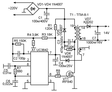
Initial nutrition for running integral chips A1 comes through a resistor R1, after which the microcircuit pulse generator is turned on, which gives them to withdraw 6. Next, the pulses are fed to a powerful shutter field Transistor VT1 opening it. Stock Change transistor feeds to the primary winding of the pulse transformer T1. After that, the transformer will be included in the operation and the pulse transmission to the secondary winding begins. The secondary winding pulses 7-11 after straightening the VT6 diode is used to stabilize the operation of the A1 chip, which in full generation mode consume a much larger current than it receives on the chain from the resistor R1.
In the event of a malfunction of D6 diodes, the source moves from the pulsation mode, alternately launching the transformer and stops it, while the characteristic pulsating "peak" is heard to work in this mode.
Power through R1 and C4 capacitor are launched by a microcircuit generator. After launch, the normal operation requires a more enhanced current. When the D6 malfunction of the additional power supply does not arrive on the chip, and the generation stops, then the process is repeated. If the diode D6 is working, immediately includes a switching transformer under full load. With the normal start of the generator on the winding 14-18, a pulsed current of 12-14B appears (at idle 15V). After straightening the V7 diode and smoothing pulses, the C7 capacitor and the pulse current arrives on the battery clips.
The current 100 mA does not harm the active component, but increases the recovery time of 3-4 times, reducing it from 30 minutes to 1 hours. ( source - Magazine Internet Edition Radio Constructor 03-2013)
G4-1h Ryobi One + BCL14181H fast charger
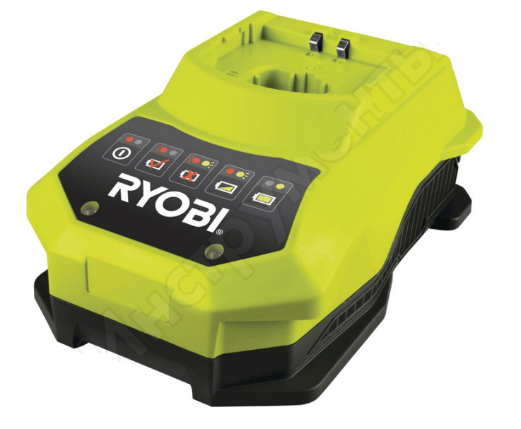 Pulsed device for lithium batteries 18 volts produced by the German company Ryobi, manufacturer People's Republic China. The pulse device is suitable for lithium-ionic, nickel Cadmium 18B. It is designed for normal operation at a temperature of from 0 to 50 C. The circuit solution provides two voltage voltage modes and stabilization. Pulse current supply provides optimal feeding of each individual battery.
The device is made in the original body of shockproof plastics. Forced cooling from the built-in fan, with automatic inclusion when 40 ° C is reached.
Characteristics:
- The minimum charge time is 18V at 1.5 A / h - 60 minutes, weight 0.9 kg, dimensions: 210 x 86 x 174 mm. Indication of the charging process is highlighted by the blue LED, the red lights up at the end. There is a malfunction diagnostics that lights up when the assembly is faulty with a separate backlit on the housing.
- Nutrition single-phase 50Hz. 220V. Network wire length 1.5 meters.
Repair of the charging station
If it happened that the product stopped performing their functions, it is best to contact specialized workshops, but elementary malfunctions can be eliminated with their own hands. What to do if the power indicator does not burn, we will analyze some simple malfunctions on the example of the station.
This product is designed to work with 12V lithium-ion batteries, 1,8A. The product is made with a downstream transformer, reduced conversion alternating current Four diode bridge circuit is performed. An electrolytic capacitor is installed for smoothing pulsation. From the display there are network power LEDs, start and ending saturation.
So, if the network indicator does not burn. First of all, it is necessary to make it necessary through the network plug in the integrity of the transformer primary winding circuit. To do this, through the pins of the plug connection of the network power, you need to ring the integrity of the primary winding of the transformer by touching the appliances of the device for the pins of the power plug, if the circuit shows a break, then it is necessary to examine the parts inside the housing.
A fuse break is possible, it is usually a thin wire, stretched in a porcelain or glass case, combining overloads. But some firms, for example, "Interskol", in order to protect the transformer windings from overheating, are installed between the turns of the primary winding of the thermal fuse, the purpose of which when the temperature is 120 to 130 ° C, break the network power supply chain and, unfortunately, it is already after breaking Does not restore.
Usually the fuse is under the coating paper insulation of the primary winding, after the opening of which, you can easily detect this item. To bring the scheme to the working condition again, you can simply discharge the ends of the winding into one, but you need to remember - the transformer remains without protection against short circuit and best of all instead of the heat to install the usual network fuse.
If the primary winding circuit is a whole, the secondary winding and bridge diodes are nicknamed. For the sounds of diodes, it is better to drop one end from the scheme and check the diode by an ohmmeter. When the ends are connected to the conclusions alternately probe, the diode should show a break, to another short circuit.
Thus, it is necessary to check all four diodes. And, if, we climbed into the scheme, then it is best to immediately change the capacitor, because the diodes are usually overloaded due to the highest electrolyte in the condenser.
Buy power supplies for a screwdriver
Any hand tools and batteries can be purchased from us on the site. To do this, you need to go through simple procedure registration and then follow easy navigation. Simple navigation The site will easily bring to the tool you need. On the site you can see prices and compare them with competing shops. Any question that has arisen can be solved with the help of the manager by calling specified telephone Or leave a question by a duty officer. Come to us and you will not stay without choosing the tool you need.
Today, many users have accumulated several workers and unused lithium batteries that appear when replacing mobile phones on smartphones.

When operating batteries in phones with your charger, thanks to the use of specialized chips to control the charge, there are practically no problems with the charge. But when using lithium batteries in various homemade, the question arises, how and how to charge such batteries. Some believe that lithium batteries already contain built-in charge controllers, but in fact, they are built-in protection schemes, such batteries are called protected. The protection schemes in them are intended mainly to protect against deep discharge and excess voltage when charging above 4.25V, i.e. This is an emergency protection, not a charge controller.
Some "self-dealers" on the site here will write that for little money you can order a special fee from China, with which you can charge lithium batteries. But this is only for lovers of "shopping". It makes no sense to buy what is easily going in a few minutes from cheap and common details. No need to forget that the ordered fee will have to wait about a month. Yes, and the purchase device does not bring such satisfaction as made by your own hands.
The proposed charger is capable of repeating almost everyone. This scheme Very primitive, but completely copes with its task. All that is required for high-quality li-ion battery charging is to stabilize the output voltage of the charger and limit the charge current.
The charger is distinguished by reliability, compactness and high output voltage stability, and, as you know, for lithium-ion batteries, this is a very important characteristic when charging.
Charger Scheme for Li-Ion Battery
The charger circuit is made on the adjustable voltage stabilizer TL431 and a bipolar NPN transistor of the average power. The diagram allows you to limit the battery charging current and stabilizes the output voltage.

The role of the regulatory element is the T1 transistor. The R2 resistor limits the charge current, the value of which depends only on the battery parameters. It is recommended to use a 1 W resistor. Other resistors can have a power of 125 or 250 MW.
The transistor selection is determined by the necessary charging current set to charge the battery. For the case under consideration, charging batteries from mobile phones, you can apply domestic or imported NPN transistors of medium power (for example, KT815, KT817, KT819). With high input voltage or using a small power transistor, a transistor is needed to install on the radiator.
LED1 (highlighted in red in the diagram), serves to visual battery charge alarm. When the discharged battery is turned on, the indicator glows brightly and as the charge dawns. The indicator glow is proportional to the battery charge current. But it should be noted that with full attenuation of the LED, the battery will still be charged with a current of less than 50mA, which requires periodic control over the device to exclude recharging.
To increase the accuracy of controlling the completion of the charge, an additional version of the charge indication of the battery (is highlighted in green) on the LED2 LED, low-power PNP transistor Kt361 and the R5 current sensor is added. The device may use any indicator variant depending on the required accuracy of battery charge control.
The diagram presented is designed to charge only one Li-Ion battery. But this charger can also be used to charge other types of batteries. It is only required to set the output voltage and charging current for this.
Manufacturing charger
1. Acquire or select from available, components for assembly in accordance with the scheme.
2. Assembling the scheme.
To test the performance of the circuit and its settings, collect the charger on the circuit board.

A diode in the battery power circuit (minus tire - blue wire) is designed to prevent the discharge of a lithium-ion battery when there is no voltage at the input of the charger.
3. Setting the output voltage of the circuit.
Connect the scheme to the power source with a voltage of 5 ... 9 volts. R3 trimmed resistance Set the output voltage of the charger in the range of 4.18 - 4.20 volts (if necessary, at the end of the setting, we measure its resistance and put the resistor with the desired resistance).
4. Setting the charger diagram.
By connecting a discharged battery to the diagram (as the inclusive LED info), I install the charging current (100 ... 300 mA) to the R2 resistor. With the resistance of R2 less than 3 ohms, the LED may not shine.
5. Prepare a board for mounting and soldering parts.
Cut the desired size from the universal board, carefully process the edges of the board with a file, clean and weigh the contact tracks.

6. Installation of the debt scheme for work fee
We carry parts from the mounting board to the working, soldering the parts, perform the missing layout of the compounds with a thin mounting wire. At the end of the assembly, we thoroughly check the installation.
I discovered that I have a certain number of well-good lithium batteries from dead mobiles, laptops, etc., which can be used in different crafts. Something they need to be charged. In the deposits, suitable details were found, and it started ...
Charger diagram
We draw a scheme, with a loaf for the presence of parts in the table box. For the sake of such a simple product lazy once again run to the store.
Limits the current, TL431 + IRF limits the voltage. Nothing special, for sure the same schemes have already drawn not one ten. Current restriction is adjusted by 125 mA based on the capabilities of the applied transformer and from restriction on heat dissipation in a small plastic case. In fact, even small batteries from mobile phones hold a much greater charged current without overheating.
The board was made quite compact to accommodate it in the available plastic case.
Assembly, testing
Retail scarf, hammer the detail. We turn on ... and hear the cry of pink Bird Oblombo no supply voltage. Familiar problem, in the Chinese transformer, the thermal stitch. I'm trying to dock to him ... and damage the wire of the primary windingSo, calmly!Of course, it is possible to solve the core, clear the turns, to discharge, insulate ... so well, I will look for something else. Successfully fell into the hands of the old, still transformer, the charger from Nokia. If you believe the inscriptions on the housing, it gives 3.7 in 355 mA, in fact, after the rectifier and the condenser, it turns out 12 V without load and 9 V under load of 130 mA. With this transformer, everything worked as it should, and on dimensions it is not more than the previous one.
Ready device

It remains to place the device in the case.
The first company, who launched into mass production, the rechargeable lithium-ion battery of a large capacity became Sony, while the battery life has become much longer than it had nickel-cadmium analogue.
Unfortunately, in the first models there was a significant disadvantage, which was manifested by the fact that at high current discharge, the lithium anode flamped.
It took about 20 years to eliminate this problem, the solution was the controller, which does not allow to form a pure lithium on the anode of a lithium-ion type batteries.
Modern models are reliable and safe, they gradually crowded off the nickel-metal hydride and nickel-cadmium batteries in portable devicesthey are installed as a power supply of a laptop, a camera, mobile phone etc.
The only niche in which lithium-ion type batteries are inferior to nickel-cadmium - these are devices whose work requires a high discharge current, for example, for screwdrivers. This type of batteries is called industrial.
Separately, it is worth mentioning the elements of Li-Pol. The only difference from the lithium polymer battery lies in the fact that another electrolyte is used in the base basis, while the principle of operation, the features and characteristics of these species are almost identical.
Features
Any type of power supply has its advantages and, accordingly, disadvantages, lithium ion batteries only confirm this axiom. Consider in detail their characteristic features.
The merits, undoubtedly, include:
- low speculation parameters;
- if you take a single element of the lithium-ion battery, the dimensions of which are equal to the batteries of another type, then it will be more charge (3.7V, in contrast to 1.2V). Due to this, it became possible to significantly simplify and facilitate the battery;
- there is no such parameter as a power memory, that is, the battery does not require regular discharge to restore power (capacity), which simplifies operation.
Speaking about the advantages that this accumulator element has, it is impossible not to take into account certain flawsTo which include:
- built-in "fuse", that is, the protection board, the task of which limit the supply voltage when charging and not allow a complete discharge of the battery, in addition to this, the maximum current is smoothed, and the temperature is controlled. Because of this, the price of lithium-ion batteries is higher than that of the analogues;
- despite the restoration of lithium-ion type batteries, they are exposed to "aging", even if they store them in accordance with the rules of operation. About how to slow down this processThis will be discussed below where the operation and its features will be considered.
Video: Overview, Opening of a lithium-ion battery from a mobile phone
Form factor
Lithium ion batteries are available in two form factors - cylindrical and tablet.


Many devices use several connected lithium-type batteries, for example, to reach voltage 12V or increase the discharge current, it must be considered if you want to buy a similar device (as a rule, the connection type is indicated on the housing).
How to charge
There are rules, thanks to which you can significantly extend the service life of lithium-ion type batteries.
The rule is the first: it is impossible to allow complete discharge, due to this you can increase the number of cycles in which charging and discharge occurs. Charged battery by 20%, it is possible to significantly extend its life, at least twice. As an example, we give the table of the dependence of the recharge cycles, depending on the depth of the battery discharge.
The rule is the second: with a frequency once every three months, it is required to produce a full cycle (that is, completely discharge and charge), due to this the process of "aging" of the batteries is slowed down significantly.
Rule Third: You cannot store a lithium-ion type battery fully discharged, it is desirable that the battery is charged by 30-50%, otherwise the restoration of its capacitance is not possible.
Rule Fourth: To charge the battery, use the original charger, which came complete from the manufacturer, this requires the difference in the battery protective circuit. That is, for example, batteries HTC, EN-EL, Sanyo, IRC, ICR, LIR, MAH, Pocket, ID-Security, etc. It is necessary to charge the Samsung battery device.
Rule fifth: You can not allow the battery overheating, the lithium-ionic device can be operated at ambient air temperature ranging from -40 to 50 ° C. With violated temperature mode It is not possible to restore the battery or produce it, it will be necessary only to replace it.
Separately, it must be emphasized that rechargeable batteries famous brands Significantly superior to the specifications of analogs of unknown manufacturers. You may not doubt that DMW-BCG batteries, VPG-BPS, SAFT, as well as original models, such as BL-5C, BP-4L (Nokia), D-Li8, NB-10L (Canon), NP-BG1 (Sony ) Or LP243454-PCB-LD will definitely better than Chinese analogues.
Homemade charger
If you wish, you can make your own hands a device that will serve to charge lithium-ion type batteries, its scheme is shown below.

Designations in Figure:
- R1- 22;
- R2 - 5,1K;
- R3- 2;
- R4 -11;
- R5 - 1kom;
- RV1 - 22kom;
- R7 - 1kom;
- U1 is the LM317T stabilizer (be sure to install on a radiator with a large area of \u200b\u200bscattering);
- U2 - TL431 (voltage regulator);
- D1, D2 - LEDs, you can use SMD type, first, signing about the start of the charging process, it is desirable to choose red, second - green;
- transistor Q1 - BC557;
- capacitors C1, C2 - 100N.
The input voltage on the lithium-ion type battery charging scheme should be from 9 to 20V, a pulse power supply can be removed for this purpose. The power of the resistors must be selected the following:
- R1 - minimum 2W;
- R5 - 1W.
- the remaining is not less than 0.1255W.
as a variable resistor RV1, it is desirable to take CG5-2 or its imported analogue of 3296W. This type allows you to more accurately set output voltage, which should be about 4.2.
The principle for which the charging scheme is following:
When turned on there is a charge Batteries, the value of the current depends on the resistor R5 (in our case it will be at the level of 100mA) the charging voltage ranging from 4.15 to 4.2V, the diode d1 sounds the beginning of the process. When the battery approaches the charging threshold, the load current will be reduced, which will turn off the D1 LED and turn on D2.
Note that when a voltage is reduced by about 0.05-0.1V, you can significantly increase the life of the battery, since it will not be charged to the end.
Contacts for charging block through which the battery will be connected, you can take from a broken device, do not forget to clean them before.
It is necessary to pay attention to that incorrect setting, for example, an overestimated voltage or charging current, one can output the batter.
The production of the charger costs much cheaper than the price of a lithium-ion battery, whether it is a city of Moscow or St. Petersburg, so save (considering how the selling them is developed), risking with the battery, using the homemade device, does not make sense.