 entrance
DIY color music from LED strip. Five-channel LED color music
Below are schematic diagrams and articles on the subject of "color music" on the site on radio electronics and radio hobby site.
What is "color music" and where it is applied, schematic diagrams of self-made devices that relate to the term "color music".
I propose two simple schemes of the CMU. The first one was collected many years ago, was repeated by several radio amateurs and did not need any adjustment. The circuit is assembled on only six transistors of the KT315 type, they, of course, can be replaced with others ... A simple, easily repeatable color music installation on symmetric thyristors and incandescent lighting lamps is described, which can be used to illuminate a hall or a dance floor, because summer is coming! It is said about color music ... This music console has a relatively high power of lighting lamps, namely: in each channel, you can use lamps designed for a voltage of 220 V (one or more), or low-voltage, connected in garlands of 220 V. Total power ... Scheme of a simple color music set-top box for working with a tube radio, bass amplifier or tape recorder. It contains a minimum of parts and is not difficult to assemble, a good option for novice radio amateurs. Connect it to the secondary winding of the output transformer. Used for power supply ... Color music scheme, the principle of operation of the installation is based on the division of the spectrum sound signal by frequency. To achieve greater variety and richness of the color pattern, instead of the widespread three-color system, it uses a four-color system (red, yellow, blue and violet) ... accompaniment of pop numbers. In this case, it is advisable to mount powerful incandescent lamps in projectors with color filters, directing them ... dynamic ranges the brightness of the lamps and the level of the sound signal, as well as the receipt of light compensation channels without any special electronic devices... The power of each of the three main channels ... Home-made color music on triacs, a diagram and a description of parts for self-production. Triacs are symmetrical thyristors that operate at any polarity of the voltage at the anode. They are used in household dimmers SRP-0.2-1. Installation - three-channel. The audio signal is fed to its input through the step-up transformer T1, which also performs the functions ... I want to present to your attention a color-music prefix assembled on two synchronous binary counters-dividers (each counter is based on four D-flip-flops), it is also a K561IE10 microcircuit. This design is readily available for repetition, the K561IE10 microcircuit can still be bought in a radio store, and radio amateurs will probably find it in stock ... The proposed simple devices are designed to create lighting effects in discos and during various entertainment events. The signals they generate can control several lighting devices, switching them almost randomly. Provided ... The peak of the popularity of color music installations falls on the 80s of the last century, now they are somehow almost forgotten. And yet, time does not stand still, and there are new technologies that can revive "color music" in a new form. Here, for example, three-color LED RGB strips or garlands ... A diagram of a simple home-made three-channel color music installation with a microphone for responding to sound in a room is given. The device is "connected" to acoustic equipment, that is, instead of a connector, there is a microphone at the input, and it perceives music directly in the room where it is ... A three-color LED strip can be used as a screen for a color music installation. The advantage of an RGB LED strip is that it can be positioned as you like, either under a matte screen or, for example, hung like a garland on a Christmas tree. Diagram of a color music installation ... This device is a typical analog light music set-top box, like those that were very popular in the 80s and 90s and are undeservedly forgotten today. The input signal is fed through a separate transformer to four active filters, dividing the signal into four ... Schematic diagram home-made color music for three channels, it is based on LM567 tone decoders, S202S02 opto-keys are used for switching. The peak of the popularity of color music installations falls on the 80s of the last century. Now they are somehow almost forgotten. And yet, time is not worth it ... The scheme of light and music on LEDs, a simple design on microcircuits K561IE16, K176IE4 for novice radio amateurs. In most cases, light and music installations are built on the basis of filters that divide the input audio signal into several bands. Then at the exit of each of the bands there is a key ... homemade device, which changes the color of the LEDs according to the ratio of the frequency components of the audio signal. This device is not fully a color-music installation, because it works in a completely different way. The color music installation at the entrance has ... Good afternoon, dear radio amateurs. This article appeared thanks to a lot of questions about ionophones of various types, sent to me after the publication of a series of articles on this topic. Especially often, questions related to tube ionophones and their improvement and further development ... In the radio amateur literature, various options for light-dynamic installations (SDU) are widely presented. For the most part, they can be divided according to the principle of operation into two different groups: these are switches for garlands (lights), operating from a clock generator according to a certain program ... Good afternoon, dear radio amateurs. Today I would like to continue a small series of articles devoted to ionophones, answering numerous requests and questions that came after the publication of previous articles on this topic. The proposed version of the ionophone is, in fact, a more powerful version ...Almost every novice radio amateur, and not only, had a desire collect color music prefix or a running fire to diversify listening to music in the evening or on holidays. In this article, we will focus on a simple color music console assembled on LEDs, which even a novice radio amateur can collect.
1. The principle of operation of color music consoles.
The work of color music consoles ( CMP, CMU or SDU) is based on frequency division of the spectrum of an audio signal with its subsequent transmission through separate channels low, middle and high frequencies, where each of the channels controls its own light source, the brightness of which is determined by the oscillations of the sound signal. The end result of the work of the set-top box is to obtain a color scheme that matches the music being played.
To obtain the full gamut of colors and the maximum number of color shades, at least three colors are used in color-music consoles:

The division of the frequency spectrum of the audio signal occurs using LC- and RC filters, where each filter is tuned to its own relatively narrow frequency band and only passes through itself the vibrations of this section of the audio range:
1
. Low pass filter(LPF) transmits oscillations with a frequency of up to 300 Hz and the color of its light source is selected in red;
2
. Mid Pass Filter(FSF) transmits 250 - 2500 Hz and the color of its light source is selected green or yellow;
3
. High Pass Filter(HPF) transmits from 2500 Hz and above, and the color of its light source is selected to be blue.

There are no fundamental rules for choosing the bandwidth or the color of the glow of the lamps, therefore, each radio amateur can apply colors based on the characteristics of his perception of color, and also change the number of channels and bandwidth at his own discretion.
2. Schematic diagram of a color music prefix.
The figure below shows a diagram of a simple four-channel color music set-top box, assembled on LEDs. The set-top box consists of an input signal amplifier, four channels and a power supply unit that supplies power to the set-top box from the AC mains.

An audio signal is applied to the contacts PC, OK and General connector X1, and through resistors R1 and R2 falls on a variable resistor R3, which is the input level control. From the middle terminal of the variable resistor R3 beep through the capacitor C1 and resistor R4 arrives at the entrance pre-amplifier assembled on transistors VT1 and VT2... The use of the amplifier made it possible to use the set-top box with almost any audio signal source.
From the output of the amplifier, the audio signal is fed to the upper terminals of the trimming resistors R7,R10, R14, R18, which are the load of the amplifier and perform the function of adjusting (tuning) the input signal separately for each channel, and also set the desired brightness of the channel LEDs. From the middle terminals of the trimming resistors, the audio signal is fed to the inputs of four channels, each of which operates in its own band of the audio range. Schematically, all channels are made the same and differ only in RC filters.
Per channel higher R7.
Channel bandpass filter formed by a capacitor C2 and only passes the high-frequency spectrum of the audio signal. Low and medium frequencies do not pass through the filter, since the capacitor resistance is high for these frequencies.

Passing the capacitor, the high frequency signal is detected by the diode VD1 and fed to the base of the transistor VT3... The negative voltage appearing at the base of the transistor opens it, and a group of blue LEDs HL1 — HL6 included in its collector circuit are ignited. And the greater the amplitude of the input signal, the more the transistor opens, the brighter the LEDs light up. To limit the maximum current through the LEDs, resistors are connected in series with them R8 and R9... If these resistors are missing, the LEDs may be damaged.
Per channel middle frequency signal is supplied from the middle terminal of the resistor R10.
The channel bandpass filter is formed by the contour С3R11С4, which for low and high frequencies has significant resistance, therefore, on the base of the transistor VT4 only mid-frequency vibrations are received. LEDs are included in the collector circuit of the transistor HL7 – HL12 green color.
Per channel low frequency signal is fed from the middle terminal of the resistor R18.
The channel filter is formed by a contour С6R19С7, which attenuates the signals of medium and high frequencies and therefore to the base of the transistor VT6 only low frequency vibrations are received. The channel is loaded by LEDs HL19 – HL24 Red.
For a variety of colors, a channel has been added to the color music prefix yellow colors. The channel filter is formed by a contour R15C5 and operates in the frequency range closer to low frequencies. The input signal to the filter comes from a resistor R14.
Feeds on color music prefix constant voltage 9B... The set-top box power supply consists of a transformer T1, diode bridge made on diodes VD5 – VD8, microcircuit voltage stabilizer DA1 type KREN5, resistor R22 and two oxide capacitors C8 and C9.
AC voltage rectified by a diode bridge is smoothed by an oxide capacitor C8 and goes to the voltage stabilizer KREN5. From the conclusion 3 of the microcircuit, a stabilized voltage of 9V is supplied to the set-top box circuit.
To obtain an output voltage of 9V between the negative bus of the power supply and the terminal 2 microcircuit included resistor R22... By changing the value of the resistance of this resistor, they achieve the desired output voltage at the output 3 microcircuits.
3. Details.
Any fixed resistors with a power of 0.25 - 0.125 W can be used in the set-top box. The figure below shows the values of resistors in which colored stripes are used to indicate the value of resistance:

Variable resistor R3 and trimmer resistors R7, R10, R14, R18 of any type, if only they fit the size of the printed circuit board. In the author's version of the design, a domestic variable resistor of the SP3-4VM type was used, and trimming resistors were imported.

Fixed capacitors can be of any type, and are designed for an operating voltage of at least 16 V. If you have difficulty acquiring a 0.3 μF capacitor C7, it can be composed of two 0.22 μF and 0.1 μF capacitors connected in parallel.
Oxide capacitors C1 and C6 must have an operating voltage of at least 10 V, capacitor C9 at least 16 V, and capacitor C8 at least 25 V.

Oxide capacitors C1, C6, C8 and C9 have polarity, therefore, when mounting on a breadboard or printed circuit board this must be taken into account: for Soviet-made capacitors, a positive terminal is indicated on the case, for modern domestic and imported capacitors, a negative terminal is indicated.

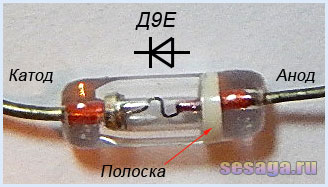
Diodes VD1 - VD4 any of the D9 series. A colored stripe is applied to the diode body from the anode side, defining the letter of the diode.
A ready-made miniature diode bridge designed for a voltage of 50V and a current of at least 200 mA is used as a rectifier assembled on diodes VD5 - VD8.

If, instead of a ready-made bridge, rectifier diodes are used, you will have to slightly correct the printed circuit board, or the diode bridge should be taken out of the main board of the set-top box and assembled on a separate small board.
For self-assembly of the bridge, the diodes are taken with the same parameters as the factory bridge. Any rectifier diodes from the KD105, KD106, KD208, KD209, KD221, D229, KD204, KD205, 1N4001 - 1N4007 series are also suitable. If you use diodes from the KD209 or 1N4001 - 1N4007 series, then the bridge can be assembled directly from the printed wiring side directly on contact areas boards.
LEDs are conventional with yellow, red, blue and green light colors. Each channel uses 6 pieces:

Transistors VT1 and VT2 from the KT361 series with any letter index.

Transistors VT3, VT4, VT5, VT6 from the KT502 series with any letter index.

Voltage stabilizer type KREN5A with any letter index (imported analogue 7805). If you use nine-volt KREN8A or KREN8G (imported analog 7809), then the resistor R22 is not installed. Instead of a resistor, a jumper is installed on the board, which connects the middle terminal of the microcircuit with the negative bus, or this resistor is not provided at all in the manufacture of the board.

To connect the set-top box with a sound signal source, a jack-type connector for three contacts is used. The cable is taken from a computer mouse.

Power transformer - ready-made or home-made with a power of at least 5 W with a voltage on the secondary winding of 12 - 15 V at a load current of 200 mA.
In addition to the article, watch the first part of the video, which shows the initial stage of assembling a color music set-top box.
This concludes the first part.
If you are tempted to make color music on LEDs, then select parts and be sure to check the health of diodes and transistors, for example,. And then we will make the final assembly and adjustment of the color music console.
Good luck!
Literature:
1. I. Andrianov "Prefixes for radio receivers".
2. Radio 1990 №8, B. Sergeev "Simple color music prefixes".
3. Operation manual for the radio designer "Start".
We all want a holiday from time to time. Sometimes you want to feel sad or to experience other emotions. The simplest and effective method achieve the desired result - listen to music. But music alone is often not enough - you need visualization of the sound stream, special effects. In other words, we need color music (or light music as it is sometimes called). But where can you get it if such equipment in specialized stores is not cheap? Do it yourself, of course. All that is needed for this is a computer (or a separate power supply unit), several meters of LED RGB strip with a power consumption of 12V, a USB prototype board (AVR-USB-MEGA16 is perhaps the cheapest and easiest option), as well as a circuit diagram , what and where to connect.
A little about the tape
Before moving on to the work itself, it is necessary to determine what this LED RGB strip with a power of exactly 12V is. And it is a simple, but at the same time very ingenious invention.
LEDs have been known for decades, but thanks to innovative developments, they have become a truly universal solution to many problems in the field of electronics. They are now used everywhere - as indicators in household appliances, independently in the form energy saving lamp, in the space industry, as well as in the field of special effects. The latter includes color music. When three types of LEDs - Red, Green and Blue are combined on one strip, the result is an RGB LED strip. Modern RGB diodes have a miniature controller. This allows them to emit all three colors.
A special feature of this tape is that all diodes are grouped and connected into a common chain. controlled by a common controller (it may also be a computer if connected via USB, or a special power supply unit with a control panel for stand-alone modifications). All this allows you to create an almost endless tape with a minimum of wires. Its thickness can literally reach a few millimeters (if you do not take into account the options with rubber or silicone protection from physical damage, moisture and temperature). Before the invention of this type of microcontroller, the most simple model had at least three wires. And the higher the functionality of such garlands, the more wires there were. In Western culture, the phrase "unravel the garland" has long become a household word for all long, tedious and extremely confusing cases. And now it has ceased to be a problem (also because the LED strip is prudently wound on a special small drum).
What we need?

DIY color music from GE60RGB2811C tape
Ideally, for organizing color music with our own hands, a ready-made LED strip powered by USB port computer. All we need is to download the required application for the same computer, set up file associations with the desired audio player, and enjoy the result. But this is if we are very lucky, and if we have the money to buy it all. Otherwise, everything looks a little more complicated.
In the sale of electronic components stores there are LED strips of various length and power, but we only need 12V. She is the best option for connecting to a computer via USB. So, for example, you can find the model GE60RGB2811C, which is a series of 300 RGB LEDs. One of the advantages of any such tape is that it can be cut as convenient as anyone - any length. All that is needed after that is to connect the contacts so that the electrical circuit is not open, and the circuit is integral (this must be done).

Color music setting scheme
We may also need a breadboard for USB connection... The most popular, cheap, but functional option for connection is the AVR-USB-MEGA16 model for USB 1.1. This USB version is considered somewhat obsolete. transmits a signal to the LEDs at a speed of 8 milliseconds, which is too slow for modern technology, but since human eye and this speed is perceived as "the blink of an eye", then it is quite suitable for us.

If we omit most of the most complex technical subtleties and nuances, then all that the scheme of such a connection requires from us is to take a tape of the required length, free and clean the contacts on one side, connect and solder them to the output on the breadboard (the symbols are indicated on the board itself, what connector and what is it for) and, in fact, that's it. For the full length of the 12v tape, there may not be enough power, so you can power them from an old computer power supply (this will require a parallel connection), or simply cut the tape. The sound with just this option will come from the computer speakers. For the electronics savvy, we recommend connecting a microphone amplifier and a small buzzer speaker directly to the AVR-USB-MEGA16.

Diagram of fastening tape contacts to a USB cable from a smartphone
If it was not possible to get this board, then in the most extreme case, the connection can be made through a 12V RGB LED strip to USB cable from a smartphone or tablet computer(the scheme for setting up color music with your own hands allows this). It is only important to make sure that the cord will give the required 5 watts of power. At the end of all these manipulations, install the SLP program (or write all the steps in a txt file, if knowledge of programming allows and the scheme and algorithm of all actions are clear), choose desired mode(by the number of diodes), and enjoy the work done by our own hands.
Conclusion
Color music is not an essential item, but it makes our life much more interesting, and not only because we can now look at the flashing colored lights that light up and go out to the beat of our favorite melody. No, we're talking about something else. Having made something like this with their own hands, and not buying in a store, everyone will feel a surge of strength from the satisfaction inherent in every master and creator, and the realization that he is also worth something. But as a matter of fact, the color music is installed, it blinks and pleases the eye with minimal costs and maximum pleasure - what else is needed? ..
 Lighting in the kitchen of a small apartment
 We select lamps for mirrors, possible options
 Airplane chandelier for children's room
It is difficult to find such a person who would not like to listen to music. To satisfy this desire, high-quality music centers, speakers and other devices are purchased. For even more pleasure, many people think about creating special color effects that can decorate any sound and create a romantic atmosphere on a date or a fun mood in the process of organizing a holiday party. Color music, like music centers, can be purchased, or you can do it yourself. The best option- to make color music on LEDs according to one of the proposed schemes.
Benefits of LED products
The modern electronics market presents a wide variety of LED strips that have a wide variety of color effects. With their help, you can create high-quality point lighting, it is possible to make color music with blinking or blurry effects.
Unlike conventional bulbs, LEDs are characterized by big amount positive characteristics. Among the main advantages of LED strips are:
- wide and varied colors;
- transfer of saturated colors;
- different design options - rulers, modules, discrete elements, RGB tapes;
- high response speed;
- the minimum amount of energy consumed.
The ribbons can be used at home, in clubs and cafes, and showcases can be effectively illuminated. This article will describe in more detail the version of LED color music for ordinary home use.
Simple circuit with one luminaire
For a start, it's worth exploring simple scheme color music. It is a device that runs on one LED, a transistor and a resistor. Power for such color music can be served from constant source current with a voltage of 6-12 volts. The device operates on the principle of an amplifier stage with common emitter... The impact in the form of a signal and amplitude varying in frequency comes to the main base. As soon as the oscillation frequency exceeds a certain threshold value, the transistor opens and the LED immediately flashes.

This circuit has one drawback - the rate of blinking of the LED depends entirely on the level of the sound signal produced. In other words, the light effect will be activated only at a certain level of produced music center volume. With a decrease in the intensity of the sound, the glow will be constant with occasional winks.
Single color ribbon scheme
This transistor-based color music is assembled using an LED strip in the load. To organize such color music, you will need to increase the power supply to 12 V, find and install a transistor with a maximum collector current that exceeds the load current, and you will also need to recalculate the total value of the resistor. Such color music is quite simple, made on one single-color LED strip and is ideal for novice radio amateurs. You can collect it without any problems at home.
Simple three-channel circuit
To get color music, devoid of all the disadvantages listed above, it is worth using a special three-channel sound transducer. Such a circuit is powered by a constant voltage of 9 V and is able to effectively illuminate one or two LEDs in each channel. Among the main structural elements that characterize such a color-musical scheme, one can note:
- three independent amplifying stages, which are assembled on transistors of the KT315 (KT3102) category;
- LEDs of different colors are included in the load of transistors;
- for the pre-amplification element, a small mains transformer of a step-down character can be used.

The input signal is fed to the secondary winding of the transformer, which, in turn, performs two main functions - it decouples two devices at a galvanic level, and also amplifies the sound from the main line output. After that, the signal goes to three parallel-located and connected filters, assembled on the basis of RC-circuits. They operate on an individual frequency band, which directly depends on the value of the capacitor and resistor.
Color music with RGB tape
This set-top box circuit operates from 12 volts and is ideal for installation on a car. Such color music optimally combines the main functions of the previously considered schemes and is able to work both in the lamp mode and in color music. The second mode is achieved due to the special contactless control of RGB tape by means of a microphone. As for the luminaire mode, it is based on the simultaneous activation of the green, red and blue LEDs on full power... The choice of the mode can be carried out by means of a special switch, which is located on a special board.
To understand how this set-top box works, it is worth studying its sequence of actions. The main signal source here is the microphone, which converts the vibrations of the sound emanating from the phonogram. The received signal is insignificant, therefore it requires amplification. This can be achieved by using a transistor or a special operational amplifier. After that, the automatic AGC level regulator starts. It effectively keeps the vibrations of the sound within reasonable limits and prepares it for further processing. Built-in filters divide the signal into three parts, each of which operates in one specific frequency range. Finally, you just need to amplify the previously prepared current signal. For this purpose, special transistors are used that operate in a key mode.

Purchase of a finished CMU
If there is no desire to make a color music for use at home, you can purchase a CMU, that is, a color music installation. This is a ready-made functional solution, which includes a controller. It will process the sound, transforming it into a light and music visual presentation. In the process of light reproduction, its intensity and color scheme will change, thereby creating the effect of a real disco. Also, the CMU device includes a panel with built-in diodes.
These devices can be based on spectral frequency decomposition, where each of them will correspond to a certain color scheme or pre-set adjustments with a variety of effects and their alternation. You can configure them using the supplied remote control.
Important! Modern CMUs are very easy to install and configure. It is the perfect solution for organizing a home party or disco.
Conclusion
There are a lot of schemes for self-implementation of color music installations. You can choose a fairly simple option, where the color of the RGB tape will simply change, to quite complex ones, which in the process of work will create a large number of various effects, overflows and fading. In direct dependence on the skills, you can choose and execute the appropriate option. It is enough to work a little and create something truly unique, it will be lighting equipment, delighting with overflows of various color shades. Also, do not forget that there is always an opportunity to buy a ready-made color music solution and fill your home with color shades and joy.
Beginner radio amateurs competition
"My radio amateur design"
Competitive design of a novice radio amateur
"Five-channel LED color music"
Hello dear friends and guests of the site!
I present to your attention the third competition work (second competition of the site) of a novice radio amateur. Design author: Morozas Igor Anatolievich:
Five-channel LED color music
Hello radio amateurs!
Like many newbies, the main problem was where to start, what would be my first product. I started by saying that I wanted to buy a home first. The first is color music, the second is high quality amplifier for headphones. I started with the first one. Color music on thyristors seems to be a hackneyed version, I decided to collect color music for LED RGB strips. I give you my first job.
The color music scheme is taken from the Internet. Color music is simple, 5 channels (one channel - white background). An LED strip can be connected to each channel, but a low-power signal amplifier is required for its operation at the input. The author suggests using an amplifier with computer speakers... I went from a complicated one, to assemble an amplifier circuit using a datasheet on a TDA2005 2x10 W microcircuit. This power seems to me enough, even with a margin. I diligently redraw all the diagrams in the sPLAN 7.0 program
Fig. 1 Scheme of color music with an input signal amplifier.
In the color music circuit, all capacitors are electrolytic, with a voltage of 16-25v. Where it is necessary to observe the polarity there is a "+" sign, in other cases, the polarity change does not affect the blinking of the LEDs. At least I didn't notice it. KT819 transistors can be replaced with KT815. 0.25 W resistors.
In the amplifier circuit, the microcircuit must be installed on the radiator at least 100 cm2. Electrolytic capacitors with a voltage of 16-25v. Capacitors C8, C9, C12 film, voltage 63v. Resistors R6, R7 with a power of 1 W, the rest 0.25 W. Variable resistor R0 - double, with a resistance of 10-50 kΩ.
I took the power supply with a factory pulse power of 100W, 2x12v, 7A
On a day off, as befits a trip to the radio market to purchase radio components. The next task is to draw the circuit board. For this I chose Sprint-Layout 6.0. It is recommended by radio specialists for beginners. It is easy to study, I am convinced of this.

Fig 2. Board for color music.

Fig 3. Power amplifier board.
The boards were manufactured using LUT technology. There is a lot of information about this technology on the Internet. I like it when it looks like the factory one, so LUT made it from the side of the details too.

 Fig 3.4 Assembling radio components on a board
 Fig 5. Checking performance after assembly
As always, the most "difficult" thing when assembling a radio circuit is to assemble everything into a case. I bought the case ready-made in a radio store.

I made the front panel this way. In the Photoshop program I drew appearance front panel where to be installed variable resistors, switch and LEDs one from each channel. The finished drawing is printed inkjet printer on thin glossy photo paper.

On the degreased prepared panel with holes, I glue the photo paper with wood glue:

Then I put the panels under the so-called press. For a day. As a press, I have a 15 kg barbell pancake:

Final assembly:


Here's what happened:


Appendices to the article:
(2.9 MiB, 2,958 hits)
Dear friends and guests of the site!
Do not forget to express your opinion on the competition works and take part in the voting for the design you like on the site forum. Thanks.
Some suggestions for those who will repeat the design:
1. You can connect speakers to such a powerful stereo amplifier, then you get two devices in one - color music and a high-quality low frequency amplifier.
2. Even if the polarity of switching on electrolytic capacitors in the color music circuit does not affect its operation, it is probably better to observe the polarity.
3. At the input of color music, it is probably better to put an input node for summing signals from the left and right channels (). The author, judging by the diagram, sends a signal from the right channel of the amplifier to the high-frequency channel of color music (blue), and the signal from the left channel of the amplifier is fed to the remaining channels of color music, but it is probably better to send a signal to all channels from the summator of audio signals.
4. Replacing the KT819 transistor with KT815 implies a decrease in the number possible connection LEDs.