 entrance
History about bugs in copiers. Electronics system, schemes when photocons appeared in the Soviet Union
Users social networks With the onset of the new year, ancient diameter (a variety of slideshows with titers) "in 2017" was excavated with the onset of the New Year. Its authors in an intelligible form tried to tell the Soviet kids, how will the world become 57 years old on the anniversary of the Great October: Robots, video call, space travel, atomic trains.
Frames from the animation film 1957:


But only in 1953 V.M. Frinjin, who had just graduated from Moscow University, created the first Soviet copying office, and later developed the theory of xerography. The future, as we know, has come much earlier than 2017, which relating to the scanners - certainly.
In the Soviet Union, copying and multiplicative devices (hectographers) were considered strategic, mandatory were recorded in the KGB, and the strictest record of the one who and where he copied was recorded.
"Erica" \u200b\u200btakes four copies - Peek in the famous song Alexander Galich (hint, as you understood, on samizdat ...)
For unauthorized use in the USSR copying and scanning technologies, it was possible to "sit" for 10 years.
The beginning of distribution in the USSR computer equipment Opened a new field for innovative developments. In the late 1980s, a group of young engineers from initiated the creation of a projection scanner.
Reference: The Russian Academy of Sciences was established by the decree of the Governing Senate of January 28 (February 8) of 1724. Recreated by decree of the president Russian Federation On November 21, 1991 as the Higher Scientific Institution of Russia. Historical milestones.
Having achieved certain success, colleagues organized a cooperative and engaged in creating and promoting their development. The result of their work was the UNISCAN projection scanner, which combined the capabilities of the scanner and a modern digital camera. He had a resolution of 72 megapixel. Such permission made it possible to see individual eyelashes on the image of a person a0 format.

Scanner on a tripod
The image of 72 megapixels in the late 80s opened
The first scanner samples allowed to get black and white images or images in grayscale grades. "Open the world in all its amazing car!" - joked in advertising prospects. Exquisite design, these models also did not differ. Later, light filters were added to the design, and from now on the scanner made it possible to get full-color snapshots.
Uniscan scanner was used to obtain and process image printing, to recognize text and creating databases, in cartography and design, to create digital copies of rare books in government libraries, for macro and microcomposition of fixed objects. The combination of the scanner with a microscope turned out to be a very popular forensic examination - Uniscan scanner turned out to be the best that was offered in the world for these tasks.

Microscope with Uniscan scanner
As far as I figured out this issue, this initiative group of young engineers in 1995 (already in the Russian Federation) founded UNISKAN LLC Novosibirsk.

Scanners for entering slides allowed to qualitatively enter information from transparent media. This is usually or tablet scanners with a special slide module, or drum scanners. Their main application is publishing and cartography. By the way, until recently, Teletip, using the principle of the drum scanner, was used to transmit pages of central publications throughout the territory of the former USSR.

Of course, we were not the first in this area:

The first drum scanner of seac *, Russell Kirsche and the scanner control panel with background. 1957, USA.
But not outsiders.
Soon "manual" scanners appeared in the USSR:

From domestic encoding devices with freely transported visits, the Pkgio is known - "semi-automatic coding Graphic information Optical "(optical part is, apparently, a visitor in the form of a magnifying glass with a crosshair and an inserted induction coil). The kit also includes an electric pencil and keyboard: double (Russian and Latin, as well as additional with Greek letters) push-button keyboard and keyboard in the form of a table with holes in which you need to poke the electric pencil - it is mounted in the tablet next to its working field. The resolution of the device reaches 0.1 mm.
I would like to note a special category of scanning (or rather copying) equipment - spyware (or intelligence).

Note: Spyings - the illegal intelligence activities of the organs (their agents) of foreign countries, which, as a rule, involves the abduction of officially classified information (state secrets) by the special services of other states.
The most famous (or rather "famous") special needs - photocopiers "Cinnamon", "Winter" and "Tan".

Photocopier "Cinnamon" (from the Keith Melton Spy Museum archive)
The effectiveness of the use of rolling devices, as well as the need for a quick and high-quality copying of a large number of documents, the developers of the NIL-11 (a specialized laboratory, which was included in the operational and technical management (OTO)) on the creation of a portable photocopier rolling apparatus for A4 format documents. In the new camera with the title "Cinnamon", the document was covered with a presser glass of the working side of the apparatus (with dimensions, as in the A4 format), and the mirror-pronance mechanism moving inside the apparatus evenly scanned the document under the action of the spring.
For uniform coverage of the document in "Cinzon" there was a special thin and long illuminator like luminescent lampswhich moved along with a mirror-prison mechanism. Its movement, as well as the transportation of the film provided a spring, which is separated by the side lever for shooting one frame. The cassette "Cinnamon" accommodated up to 400 frames with a standard 35 mm film film and could quickly be replaced with a "fresh" light in a few seconds, which gave the ability to copy a large number of documents. The lens diaphragm was selected depending on the sensitivity of the film. Cinnamon had a personnel counter, as well as a comfortable shutter lever, which worked from both the right and left hand. For powering the illuminator "Cinnamon", a standard power grid 110/220 volts could be used, as well as a 12 volt voltage through a car cigarette lighter connector.

Set of a "Cinnamon" apparatus (from the Keith Melton Spy Museum archive)
"Cinnamon" turned out to be a very effective device for quick copying a large number of documents, for example, when the officer-curator received secret documents through a cache from his agent for a fairly short time, copied them in the car, compliance with the requirements of conspiracy, and after completing the work, the agent returns them back A pre-agreed way. Cinnamon was also actively used on conspiracy apartments and in hotels, where the documents received during the time were delivered and after photocopying were returned to the official storage sites. The dimensions and weight of "cinnamon" together with the power supply unit and in advance the cassettes are allowed to transfer the entire set in the usual portfolio or in the attache-case, which ensured the conspiracy of the entire event of working with the device both in the car in the parking lot or movement and to shoot documents in room.
Operational divisions of the KGB actively used "Cinnamon", noting simple setup And the convenient control of the device, in connection with which the serial production of "Cinnamon" was organized at the Krasnogorsk plant, where the device was assigned the factory index C-125.
Later, the operational units of the KGB arrived a prototype "Cinnamon", designed to use 16 mm film films with an electric motor for the drive of a mirror-pride-called system and a film transportation mechanism. The new apparatus "Winter" was smaller in size and provided copying the A4 document twice with the overlapping of each shelter. The "winter" cassette was designed for 400 frames, accommodated 6 meters of 16 mm of photographs with double perforation and sensitivity from 45 to 700 units. GOST. The photographing of one frame began after shifting to the right lever-switch with a thumb right hand, and was produced for 2.5 seconds. Included in the "winter" power supply blocks provided the operation of the device from the 12 volt automotive network and from the standard power grid 110/220 volts.
Despite smaller dimensions and the presence of an electric drive, the "Winter" apparatus did not take active application in operational practice. According to the KGB officers, the device often lay in places of storage of operational techniques and was removed only for the annual inventory. According to experts, copying the A4 document turned out to be inconvenient, and many operatives preferred old "Cinnamon."

Photocopier "Winter" (from the Keith Melton Spy Museum archive)
In the mid-1980s. The prototype "Cinnamon" and "Winter", the camera "Tan", to copy a complete A4 sheet to 16 mm, a photofill with the electric drive of mirror-prideful mechanisms for scanning and transporting the film.
The tanning cassette was designed for 400 frames, two more cassettes were also included. Thus, the "tan" could provide a relatively fast copying of more than a thousand sheets of documents.

Photocopulating apparatus "Tan" (from the Keith Melton Spy Museum archive)
However, the new "tan" did not receive active use, possibly due to relatively large weight (more than 3 kg) and increased dimensions, which was most likely inconvenient for operational officers in the case of transportation of "Zagar", which was already faced with difficulty Standard portfolio. In the second half of the 1980s. The active use of computer scanners began, on which copying compared to the bulky "tan" was much easier. All this led to the fact that the factory batch of Zagarov did not find applications. New sets of this device were kept in warehouses of operational equipment for a long time, until the indication of sending the entire batch to the NIL-11 to destroy or the possible use of individual blocks, nodes and parts.
This ended in a very effective use of the KGB divisions of the KGB camera of rolling, which gave a lot of documents necessary and especially important to the USSR, including copies of materials on rare languages, when the requirements of the high definition of the obtained negatives were particularly presented. Today, in the arsenal of modern intelligence, there are a variety of household digital devices that allow without any camouflage, it is quite open and easily scanning documents and drawings of any complexity.
By the way, the Space Activities of Luna-9, Luna-13, Side Cameras of Moonholders, Camera Venger, can be attributed to scannes. And the real scanner can be considered the moon-19 and -22. The chamber was a linear photosensitive element, which scanned the image moving under the moon surface apparatus. Snapshot:


Today, without scanners, we can no longer submit our normal life:

Computer processing of photos in the USSR (1987)
That's all that I managed to accumulate about scanners in the USSR.
Maybe someone knows more?
Thanks for important clarifications. [Email Protected], @ hoegni, @petuhov_k and @rumlin
Example mg of the storage engine of the copier.
Professional repairs assumes that the specialist knows the principles of construction and work of the repair facility.
The main engine in this copy is made as part of the drive module with the appropriate gearbox. The module is fixed on the copier housing in a specially designated place with multiple screws. The engine rotor rotates (through the appropriate gear ratios of the gearbox) two gears, one of them drives the driver-unit cartridge, the second is the shafts of the toner fastening and paper rollers. Module control and power signals come to the motor control board from the main copier control board, on the connector marked as CN1.
The engine used in this copying unit relates to the type of DC necolettor engines (or, in other words, to spindle engines), which is managed using a special chip (engine driver).
Constructively, the engine consists of a stator with a certain amount of windings and a rotor with a constant multipole annular magnet. In our case, in order to reduce the step and reduce the rolling torps, the number of windings is increased to 9, i.e. One phase has three windings (see Fig. 1).
Fig. 1. The design of the main engine of the copier.
The engine rotor is located outside and has a permanent ring multipole magnet, and windings are located on the stator, which are fixed on the board (this engine design is called "facing"). To rotate the rotor, you need to skip the current through the stator winding in a certain sequence. The power of the stator windings is carried out in such a way that there is a displacement of a certain angle between the magnetizing force (created by the stator) and the magnetic flux, i.e. A rotating magnetic field acting on permanent rotor magnets is created. As a result, the rotor consisting of an annular multipole permanent magnet begins to move after the magnetic field of the stator and rotate. Rotation of the rotor can continue only as a result of switching stator windings. Moreover, when switching, two conditions must be performed, according to which the stator windings should switch at a certain point and with a given sequence. The position of the rotor is determined using the position sensors, which use three Hall sensors. At the output of each of these sensors, differential signals are formed, which show the force and direction of the magnetic flux in the place where the sensor is installed. When the rotor rotates, the signals from the Hall sensors are sinusoidal voltages. Based on the analysis of signals from the Hall sensors, the microcircuit - the engine driver connects one or another phase of the stator.
The power of the magnetic field determines the power and speed of the engine. By changing the strength of the current through the windings, it is possible to change the speed of rotation and torque of the engine. The most typical method for adjusting the current force is the control of the average current value through the winding, which is performed by pulse modulating the supply voltage of the windings by setting the durations of feeding and removing the supply voltage. Thus, to achieve the required average voltage value and, as a result, moderate current. The speed is usually set in two ways: a reference pulse signal or an adjustment of the current through the winding of the engine. Schematic diagram of the engine board is presented in Fig. 2.
Fig. 2. Schematic diagram of the control board of the main motor of the copying machine.
From the main control board on the motor module, control signals can be seen on the CN1 connector. Using these signals and ensures the engine management. Connector contact numbers, their designation, as well as functional purposes are presented in Table 1.
Table 1. Assigning CN1 connector signals
The engine speed is determined by the inductive type speed sensor, the windings of which are made in the form of a printed mounting (under the rotor magnet on the printed circuit board, the melastel tracks of the conductor, forming an inductance coil, in which the EMF is replaced when rotating a constant annular magnet rotor).
The motor phases on the diagram are indicated W1, W2, W3, each phase corresponds to two windings on the engine stator. The position of the rotor is monitored by three Hall sensors, which are indicated on the Scheme of Hi, H2, NZ. Winding management is performed by the output cascade implemented as part of the control chip. The formation of control signals for the engine, as well as current control in the windings and the management of them is carried out (as we have already noted) through a specialized chip (driver) LB1920. The LB1920 chip (see Fig. 2) is intended for controlling a 3-phase uncoolette engine. It can be attributed to its features:
- Wide range of operating stresses: 9 - 30 V;
- the ability to work with currents, values \u200b\u200bup to 3.1a;
- the presence of built-in protection against excess current;
- the presence of a built-in control circuit of the Hall sensor;
- the presence of digital speed adjustment;
- the presence of output of external lock (S / S);
- the presence of built-in protection against overheating of the chip crystal.
The internal structure of the LB1920 chip and the distribution of signals over the contacts of the chip is shown in Fig. 3. Assigning chip contacts, input and output signals are described in Table 2.
Fig. 3. Internal structural scheme Main Engine Drivers LB1920
Table 2. Purpose of the LB1920 control microcircuit signals
Considering the trend of manufacturers to apply spindle engines in many nodes of devices (for broaching paper, in the drives of toner fixation nodes, in the laser scanner blocks, etc.) we hope that this material will be useful to repair and service personnel.
The location of the resistors on the boards of these devices is shown in Figure 2.53
On the board of the control panels that are not equipped with an automatic exposure sensor, the trim resistor is located otherwise (Figure 2.54)

The following figures show that only one of the rates on the control board is common to the entire series - in the conceptual circuits, it is indicated as VR604 and serves to change the intensity of the scanning lamp. It must be configured primarily, after turning off the automatic exposure adjustment mode, if such in the device is provided.
This setting is performed by light turns of the rotating disk of the trim resistor with a thin screwdriver or just with a finger, since the disk design allows. After each change in the position of the disk, you should run a copy and determine on it, in which direction and how much it should be turned it.
If the copy is too dark, with the so-called veil on the background, then the VR604 must be rotated to the right, clockwise.
If the copy is overlaid, thin lines on it are lost and the total contrast is insufficient - the VR605 is rotated to the left, counterclockwise.
For precision exposure reciprition, a special test sheet is used for copiers, on which the scale of accurate gray grades is located (see it in section 1.4).
When using the VR604 setting will be able to force the device to produce in manual mode copies best quality, You should go to the automatic exposure adjustment, and if it is not provided with the design, then complete the procedure by returning the removed cover of the control panel to the place.
For rough adjustment of the automatic exposure sensor, you can act in the same way as when setting up the VR604, that is, rotating the VR602 and VR603 discs until the optimal copy quality is reached when the AE control panel is turned on. With certain skills it is quite possible to configure the automatic exposure, even without a test sheet and multimeter.
A more scientific way to set up an automatic exposure consists of the following steps:
1. Turn off the power of the copier.
2. Remove the control panel cover.
3. Rotate trimming resistors VR602 and VR603 clockwise until it stops.
4. Place the original to the exposure glass, evenly filled with text with a thin design of letters and does not contain large voids, no areas of black color, for example included in the text of the illustrations. Best of all the newspaper is suitable for these purposes. The original should close the automatic exposure sensor window located in the central part of the copier (Fig. 2.55).
5. Sort the three jumpers JP607, JP605 and JP604 simultaneously on the control panel board using a slot screwdriver, as shown in Fig. 2.56.

6. Continuing to hold jumpers connected, turn on the power of the device. The engine of the machine will start rotation, the number 0 will appear on the number of copies indicator, and the scanning lamp will light. At this point, jumpers should be released.
7. Take a digital multimeter, adjust it to the range 20 in DC and measure the voltage between the anode diode D606 and the jumper JP607 (Fig. 2.57)

8 rotate the VR602 trimming resistor until the voltage on the multimeter indicator is 4 V with a maximum error in 0, 1 in
9 Replace the newspaper on the exposure glass on a small stack of clean paper sheets and repeat the measurement of the voltage between the D606 diode anode and the jumper JP607. Now the VR603 should be rotated until the multimeter shows about 1, 8 V with the same permissible error in 0, 1 V.
Note. Since in each particular case you need to take into account the differences in the state of the working components of the device, which can somehow influence the level of automatic exposure, sometimes it is somewhat corrected by the multimeter exposure. If the quality of copies in automatic mode After adjustment, it turns out perfect, you should immediately go to the last, thirteenth, paragraph procedure.
10. Reset the adjustment mode by turning off and on the power supply of the machine.
11. Place the newspaper, test sheet or any other original and check as far as auto exposure is exposed to exposurely.
12. If despite the adjustment, the copy is overwhelmed with light, it is necessary to slightly shift the VR602 counterclockwise. If, on the contrary, a copy is too dark - slightly shift the VR602 clockwise to repeat these actions until the optimal copy quality has been achieved with the automatic exposure measurement. To completely eliminate the danger that the wrong selected original will cause incorrect adjustment, this stage It is recommended to use several different originals and to check the results obtained on them.
Occasionally, when you have to replace the defect card of the control panel, and at the same time it is precisely known that its electrical part related to exposure control is unharmed and properly adjusted, you can set the parameters of the new board in accordance with the old resistance.
Many prefer this not to do and every time in such cases exhibit the exposition re-(see above), but since such a way exists, it is reasonable to briefly describe it.
1. Disable the power cable from the power supply.
2. Remove the copier, control panel cover, top panel and, finally, a defective fee.
3. Immediately mark it in order to accidentally not confuse in the measurement process, which often happens in practice, especially when none of the compaable boards has noticeable differences.
4. Install the multimeter on the range up to 200 kΩ and measure on old board Three resistance:
a) between the top contact VR602 and the jumper JP607;
b) between the top contact VR603 and the jumper JP621;
c) between the top contact VR604 and the upper contact of the resistor R614 (Figure 2.58)

5. Get exactly the same resistance on the new board by rotating the corresponding trimming resistors.
6. Install a new board in the device and check how correctly manual and automatic exposure are adjusted.
Note. In devices that are not equipped with an automatic exposure sensor and having only one trimmer VR604, on the fourth step of the previous procedure, only the resistance between the upper end VR604 and the lower contact of the resistor R614 should be measured (Fig. 2.59).

2.4.5. Image transfer system. Spongy ship
After the rays of the light, reflected from the original, fell on a pre-negatively charged photoreceptor and formed a hidden electrostatic image on it, and the toner particles from the magnetic shaft were pulled and showed this image, it is necessary to transfer it to paper.
For this, it serves as installed on the window of the apparatus, to the left of the margin of registration, spongeous shipping. During the copying process, a negative charge is formed on it, which attracts toner on the drum. And since at this time there is a sheet of the supplied paper between the shafts, the entire toner falls on it and creates a copy of the scanned image.
After that, the paper is discharged by needle-honest, so that static electricity makes it bend during further movement on the feed path, and is fed into the thermoblock, where the toner is compiled into its surface, forming a final copy.
If the sponged didorny was not negatively charged, but only a function of the climb passing over it was performed to the surface of the phototraban, adhesion toner and paper would not be enough to overcome the toner attraction to the drum, and the copy would be practically white.
Actually, this is how the malfunction is manifested in the chain of the shipping chain of the transfer. If at initial diagnostics of the fault, it is noted that it is preferably white sheets (or with very weak pictures of the image) and the combined E-16 / E-30 cartridge is not to be definitely definitely definitely definitely, it is necessary to find out whether the voltage is supplied to the shortage of transfer or not.
Undoubtedly, in some cases, the voltage is not fed to the bitron due to problems in the power supply. However, mainly the reason for this is a contact of the contact at the satellite seat with an output on the power supply board. The shorter is powered by a spring in the near end, directly connecting its metal shaft with a power supply board.
Most often, the contact is broken due to the springs of the spring from the bare contact on the board.
Sometimes, in order to save time, when repairing electronics of the power supply unit, the wizard includes an apparatus for checking not only without returning the lower case panel to the location, but even without tightening the screw-fastened screws. In such cases, the front end of the board saves slightly, as a result of which the coating springs of the Cordaron can lose contact with the board.
As a result, the sheet will be cleaned clean, and if the contact of high-voltage conclusions will be disturbed, the copy may turn out, on the contrary, very dirty. This feature should be remembered: if it is seen that unusually contaminated copies have begun from the device, then first of all it is necessary to check the contacts on the closest side of the combined board, and not attempt to adjust the exposure, clean the optics or replace the cartridge.
In such cases, to exclude violations of the Master's contacts, who know about this feature, usually gently press the edge of the printed circuit board with a hand, which can not be an example for imitation, because in the immediate vicinity on the board there is a high voltage and such sings may end. It is better to spend a few seconds to install screws than every time you have to get a high-voltage discharge at risk.
If all the screws are fixed, but there remains doubt whether the contact of the spring is sufficient, it is possible to stretch the spring, delivering the bitter from the fixtures in the device.
Sometimes the near end of the board, even fixed with screws and latches, still continues to be exhausted. In my practice there were cases when for absolute confidence that contact in the future will never be broken, it was necessary to drill additional holes in the device to install another screw, pressing the most edge of the board and thus excluding even the slightest danger of its savory.
The sponge of the spongy shipping of the transfer can lose contact with it in its upper part. In this case, you should again remove the Cahron and, clearing the place of their connection, ensure reliable contact.
If necessary, spongeous transfer of the transfer is extracted from the device as follows:
1. To gain access to the paper path, leak up the top door and install it vertically.
2. Out in turns of symmetric plastic hooks 1, retaining from both ends of the sleeve of a charter of transfer, raise the shorter 2 and remove it from the machine (Fig. 2. 60).

Note. Special attention should be paid to the springs supporting the bitter bottom. When removing the spongy border, it is necessary to act carefully to prevent their loss.
3. With the subsequent installation of the Corrieron to the place to trace so that the springs stood smoothly and both ends of the Sponge Cordroon were spanging quite well, while at one level it is not necessary to clean the spongy surface of the Cumoron, as a rule, it is not at all necessary, because it completely loses its properties at all strong pollution Toner falling on it.
If the master is still going to do this, it should be remembered that solvents or water can not be used here. Wipe the spongy surface need a dry cloth. Typically, it accumulates so much toner in its pores that this procedure can take a long time, so it is recommended to remove the excess toner with a slight tapping of the honend along the edge of the table or - if the wizard has a vacuum cleaner - spending the honer and only then clean it, using a dry cloth.
2.4.6. Determining the state of the upper door of the device and the door of the thermoblock. SW1 and SW2 microspectors
To avoid using a copier in open video, as well as in the interests of observance of safety, the position of the upper door and the release door of the thermoblock is controlled by sensors that turn off the power of the device as only the doors open. In this case, the backup power of the processor comes to it through the auxiliary transformer T101, even when the power button is not yet pressed.
In the devices of the RS-400/420/430 and FC-200/220 series used new systemdetermining the condition of both the apparatus door using a common microswitch and a mechanical lever fixed on the top plate of the thermoblock. By your device, this lever is quite reminded by a combined front door recording lever, a toner cartridge and power switch in the Sharp Z-52 clone copiers.
In older RS-300/320/325 and FC-200/230 models to control the position of each door, separate SW1 and SW2 microswitters are used, of which the first is mounted on the right side of the copier, near the feed assembly, and the second that is only responsible for the release door Thermoblock, installed exactly there, where there is a common sensor on new models. With such a system, microswitches are located in the chain sequentially, due to which the unconditional shutdown of the power supply is achieved if at least one of them does not provide contact.
When repaired, it often makes it necessary to turn on the device with a removed top panel to be able to directly control the operation of the internal nodes. At the same time, the sensors cease to be fixed in the usual way, and they have to be clamped manually. The upper door sensor in the most predominant devices that the older series are most convenient to fix it, after pressing it and pressing it down so that the closing protrusion is pressed by a pressed plastic bed. During the final assembly of the apparatus, it is necessary to return the microswitch SW1 back, otherwise it will be a direct impaired safety technician that allows unknown operators to freely access nodes that are in working condition and to the outputs of high-voltage voltage that goes to the E-16 / E-30 cartridge.
It happens that the reason for the defect in the repair of the copying apparatus is lacking in the repair of the copying apparatus - it lies in the exterior door sensors.
In such situations, the first thing should be checked how good the microswitters and the value of their wiring are closed. To do this, the easiest way to use the multimeter mounted in sound transverse mode is the same.
Sometimes due to rust or due to the fact that, for example, the SW1 sensor was flooded with an electrolyte from the bundled capacitor on the power supply board, the contact defect is randomly manifested, in other words, has a "floating" character. Therefore, it is recommended to check the contacts of the switches very carefully, imitating the cycle of their closure to several tens of times in a row. And even in this case, there is a small chance that the defect, without being seen by the repair by the engineer, will still appear in the future.
The reason for the non-SW1 and SW2 sensors can be mechanical damage Room adjacent to them. At a certain number of disorders of electrical contacts accounts for an average of the same number of disorders of mechanical contacts of parts.
The most frequent mechanical defect system for determining the door position in a similar CANON PC / FC-310/330/336 series was a bummer of one of the hooks on the thermoblock door, because of which it stopped sufficiently firmly to the body of the apparatus and the SW2 sensor was blocked. Fortunately, in the models of the real series of the thermoblock, the door of the thermoblock is somewhat different, which practically eliminates the emergence of any problems associated with it.
Here the defect of the complex-composite design, fixed from the inside of the upper panel, is most common and designed to serve as a gearbox when the SW1 sensor is closed. The design includes a metal plate, a plastic part and spring, interconnected rather unreliable and failing to be in many different reasons. Accordingly, when making decisions, it is necessary to improvise.
It is often encountered another defect when determining the position of the upper door. Over time, the mechanism is loosened, and its parts are slightly erased, so that the top door in the closed state turns out to be literally on the line of millimeter insufficient to close the contacts of the SW1 microspector contacts.
In this situation, solutions may be several. Many masters go to the old proven route of gluing small squares of plastics to compensate for the armed play on the lower surfaces of the recess of the upper door, which in the closed position is held by latches. At the same time, it is necessary to ensure that the edges of the glued plates do not protrude beyond the edges of the recess, otherwise the latches when closing the top door will constantly hurt behind the plates and eventually cut them out of the door recesses, as a result of which the defect will begin to appear again.
Let me remind myself once again that all this applies only to those series of series in which separate sensors are installed for each door.
The mechanical defect of the sensor standing on the thermoblock appears only in one case - when from plastic casing, in which it is installed and by which the latch is mounted on the thermoblock. The casing along with the latch is made of not enough plastic material and it breaks easily, especially with inept attempts to remove it from the thermoblock when, pressing the latch, it takes it on the break. In the future, the broken casing can spontaneously shift and exit the slot of the thermoblock, the closed release
the door will stop closing the thermoblock and the power of the copier will not turn on. The method of repair is obvious. It is required to remove the upper panel of the device and replace the microswitch cover. If a broken latch is found in the device, you can try to glue it into place, but the connection strength is not guaranteed in this case.
2.4.7. Manual exposure controller damage
With a negligent installation in place of the top panel of the device it is easy to damage the disc regulator on the control board manual setting Exposure.
The plastic disc with divisions is attached directly to the VR601 trimmed steps in charge and with a properly installed top panel partially towers over it. The hole under the disk in the top panel is very accurate, without unnecessary gaps, and with the slightest error made in the installation of the panel, the disk dimensions may not fit into the hole. In this case, the effort that the wizard collecting the machine is attached to the front of the panel to fix it with latches, it may be directed to the disk of the manual exposure regulator and damage the resistor to which the disk is attached as the most fragile part of the design.
Unfortunately, the copying equipment is quite often subjected to unqualified intervention, so this defect is quite common.
He is noticeable and manifests itself in the fact that the disk manual adjustment of the exposure or is completely recessed under the top panel, or it is very unreliable and when you press it with your finger, it varies noticeably. As for the manual exposure itself, then the consequences can be the most different: it is possible that it will still be fully adjusted, or with some positions of the disk, failures will be displayed, or it will not be adjusted at all.
To eliminate the defect, you must remove the copier, the control panel cover and the top panel to access the control panel board and the regulator installed on it.
The Plastic Case VR601 is maintained from below with two thin metal hooks. They are bent primarily when applied to them excessive physical strength. As a rule, to eliminate the fault, it is enough to press the hooks and return them to a horizontal position, after which the regulator turns out to be in the desired position and stops staggering, and the resistor begins to be adjusted again. When assembling the device, it is necessary to install the top panel especially carefully to put the top panel in order not to damage the already weakened design of the regulator again.
If the damage is too serious so that it can be fixed in the manner described above, the trigger resistor should be replaced, dropping it from the board. It seems inappropriate to change the entire fee of the entire fee, especially since here Canon retreats from its policies to replace damage with whole nodes and expresses the readiness to supply elements of the control board separately. Designation VR601 by Canon Spare parts catalog: VR9-3619-000 VARIABLE Resistor, 10 Kohm.
2.4.8. Power Supply. Short description. Weak spots
As practice has shown, the most weak point of the power supply was the auxiliary T101 transformer, which is constantly feeding the processor when the power cable of the device is enabled in the power supply.
The transformer is located at the far end of the board and has seven contacts. As a rule, he burns only the primary winding. When it is damaged from the device, it can go whitish smoke and spread the smell of burner isolation. When opening the device, the blackening of the transformer itself is usually noticeable immediately and the characteristic flare on the board under it and around. Naturally, the first thing is necessary to check the resistance of the windings to make sure their cliff.
The primary winding is nicknamed on extreme contacts, secondary - in the second and fourth. In the devices at 220/240, the primary winding resistance is about 3, 7 com, and the resistance is secondary - 12 ohms. In the devices for 110/115 to the primary winding, respectively, has approximately twice as long as resistance.
After checking the resistance of the transformer, it is necessary to find out which voltage comes from the secondary winding of the transformer on the fee. It must be within 6 ... 16 V for different devices. The output of the voltage from the specified range due to disorders in the transformer winding may, for example, be the cause of the appearance of frequent transverse white bands on the copies.
In models on 110/115 in which the domestic market is saturated, this transformer is constantly burning with the inclusion of devices by inattention into a normal network without using a downcast transformer 220/110 V.
The burned transformer should be replaced with a new or rewind damaged winding - depending on the capabilities of the service center or private wizard.
By parts catalog, the T101 transformer can be ordered as FH3-0749-000 Transformer (100/115 V) or FH3-0753-000 Transformer (220/240 V).
The main, impulse, T106 transformer can also fail. If there are doubts about his serviceability, then after eliminating all other noticed damage it is recommended to replace the working and look at the result. Due to the fact that the impulse transformers burn out far away in the first place, they are not a deficit and in each service center probably there are at least some good T106 on the charged cards. It can be recommended to always have a spare transformer for verification at hand.
Fuses FU101 and FU102 are also burned very often. The first of them has a rated voltage 250 V and for current 2, 5 A in models at 110/115 V and 1, 6 A in models on 220/240 V. The second fuse may have a nominal 125 V, 10 A (110 / 115 B) or 250 V, 2, 5 A (220/240 V).
Before replacing the fuses, it is necessary to find the cause of their damage, because it rarely happens that they are out of order only because of the external voltage jump, and all other parts remained in good condition.
The diode bridge Q147 is damaged relatively rarely, but still it makes sense with complex defects of the power supply of the power supply, it does not bother first from the board. If all other elements are working, the multimeter should show conventional resistance. And only in the case when the bridge is broken during the draft bridge, it will have to be filled and checked separately. Often the diode bridge is a whole, and the cause of a defect detected during its initial check is some other item, for example, punched field-effect transistor Q158. If the diode bridge itself is defective, then it should be replaced by removing from another board, picking up an analogue or ordering by the name Diode, Bridge, D2SB60 and the number according to the WA1-0762-000 details catalog.
Very frequent cases when the key transistor of the pulse transformer Q158 is out of order. It is installed closer to the far end of the board, close to the metal plate of grounding, to which is rigidly attached using a pressure plate on the screw. To prevent electrical contact of the transformer with a presser plate, is an insulating rubber gasket. Contact from the ground plate is needed only to remove heat from this powerful and highly heating transformer.
When fails, the transistor Q158 usually closes short, which can be determined and without dropping it from the board. At the same time, as a rule, a fuse burns, and the diode bridge starts almost with zero resistance to ring off the plus for minus.
With comprehensive power supply defects, the Q158 transistor should be checked almost first.
To replace the key transistor, it is necessary to unscrew the screw from the ground plate, remove the pressed transistor plate and rubber insulation and then drop the transistor from the board.
In the apparatus for meals 110/115 V, this field transistor has a nominal value of 2SK1202 and the WA2-5006-000 catalog number. In the devices for 220/240 V in position Q158, there is a transistor 2SK1317, whose catalog number WA2-1527-000.
The reason that the copier does not turn on, are often protected transistors Q148 (2SD2088, Catalog number WA2-1348-000) and Q149 (2SA950-Y, Catalog number WA2-0317-000), having feedback with a pulsed transformer. They are difficult to check, even having fallen, because they can be called almost as good, but without their replacement, the defect will not succeed. There are their domestic analogues of KT502B and KT503, which are quite suitable, but they have an emitter, the base and collector are located in a different way, so that it is necessary to encourage contacts accordingly.
Sometimes, along with these transistors, diode D137 burns, as well as resistance with a face value of 18 ohms, position on the R284 board. As a rule, the field transistor Q158 burns with them, which has already been discussed. Occasionally, pair capacitors C194 and C195 and the pulse transformer itself is damaged.
Finally, it is worth mentioning some of the defects of the power supply, due to which the device does not cease to be turned on, however, it fails to work. These defects are also sufficiently common.
It happens that the copier with an absolutely serviceable cartridge, which is properly adjusted by the control / exposure panel and good contact The conclusions in the near end of the board begins to constantly give out a black sheet.
The reason lies most likely in the high-voltage power supply circuit. It happens that the high-voltage diode D129 (DIODE, SHV-02) explodes, leaving after himself only two punches in the contact fee, and just this leads to such consequences. It is desirable to have some stock of such high-voltage diodes, because sometimes defects begin to manifest literally one by one. On the same combined board of the power supply unit of the devices of this series there is about ten such diodes, so it usually does not arise about the need to specifically buy the necessary reserve - it is enough to have a pair of not subject to recovery boards from which parts can be trapped.
Occasionally on the machines of the series begins to manifest the following unusual defect: Copies are properly made, but at the end of the copier cycle, the M1 engine continues to rotate on small revolutions. In this case, attention should be paid to the engine control loop on the power supply board, especially for three next parts (designation for spare parts corporate catalog):
Q102 IC, UPC339C, COMPARATOR WA4-0041-000;
Q115 IC, M51971L, Speed \u200b\u200bControl WA4-0558-000;
Q121 TRANSISTOR, 2SD1593 WA2-1434-000.
When violations in the scanning lamp, when it is not turned on, or it is on constantly, starting from the moment the power supply is turned on, you need to check the 2SD2165L scanning lamp control transistor (WA2-6008-000), located on the board in the Q143 position. It is easy to notice, because it is attached by a screw to the zigzag tin plate, also soldered in the fee. The Q143 transistor must be ringing from the collector to the base and the emitter and from the base to the emitter and the collector. If the multimeter indicates the presence of conductivity between the emitter and the inputs of the transistor, the transistor needs to be replaced.
2.4.9. Damage in the electronics system caused by insects
The greatest danger for copiers (after the voltage shots in the network and the incorrect actions of the operator) are cockroaches.
Too often, the management of firms looks through the fingers to the unsanitary state of the jobs of their employees and does not take any measures on periodic disinsection. More than others suffer from this small devices, cheap and therefore accessible to all, ranging from the heads of food warehouses and pro-workers. These devices are most often used in places inappropriate for office equipment.
Such a negligent attitude to the recommended operating conditions is poured for the owners of technology in constant spending on expensive repair work. For repairing a copier transformed into insect nests in service centers It is sometimes taken a triple price, otherwise they refuse to repair. Few people are pleased to collect dead cockroaches with a vacuum cleaner, and often and captured in the complex interlacing of the nodes of the device of living individuals.
The owner of the apparatus applying for warranty repairs, the more should take care so that the master does not find inside the copier not the slightest trace of insects insects, otherwise it will have to pay in full swing.
Therefore, it can be recommended to all owners of copiers do not save funds to maintain purity in places of use of complex office equipment so that there is no need to spend significantly large amounts for its repair.
Cockroaches use copiers and as shelter, and as a heat source, especially preferring thermoblock and heating when working electronic components On printed circuit boards. At the same time, they closure contacts on the latter, which often leads to very serious complex electronics defects, at which there is a tent of radio components.
The location of the thermoblock and printed circuit boards inside the copier is very important. If the thermoblock rests on the base of the machine's bed, and the boards lie horizontally, like, for example, the combined processor / power supply board in the devices of this series, insects will feel there quite freely. If the board are placed vertically, and the thermoblock is suspended on the top, folding part of the bed, as in the CANON NP-6012 clone models, described in the fourth chapter, defects caused by cockroaches, will almost not be.
The functioning of the copying apparatus cockroaches may affect the most unexpected way. In this respect, there is one case from my practice. Putting another portable Canon on the desktop and referred to the defect declared in the repair sheet, I began to initial testing the device. The device showed the paper jam and refused to issue a copy. Removing the exposure glass and the top cover to check the status of the output sensor, I found the living cockroacine sitting in its optocoa. The insect felt there as at home, and was not going to leave the spaced place. Removing it from the device and foaming the optocoupler with a tassel, I collected the device, confident that now everything will work. Not there was something. Indication of jams resumed with the former intensity. Since the correct operation of the output sensor was already secured, I began to disassemble the copier on the other side to get to the optocoupler of the registration sensor. After removing the bottom panel and throwing into the combined board of the power supply, I found in the second from the device sensors the exact same large alive cockroach.
It is difficult to say that attracted insects in optocoules - generated radiation or convenient form, but the situation was rather funny. After expulsion of the second insect, the device earned.
2.4.10. List of symbolic designations, digital and analog drive signals
1. Symbolic notation in diagrams and tables
Intr. Rollback of the copy table in the starting position, in the process of which the gearbox mechanics makes a return movement
Lstr. Final cycle in table motion
CBFW. Translational movement of the table, during which a copy process occurs
CBRV. Returning movement of the table
StBY. Idle mode of operation of the device at which no copy is made
2 digital signals in binary system (Take values \u200b\u200b1 or 0)
ASVTR Synchronizing displacement signal alternating current
CBSD. SL2 gearbox solenoid activation team
DCBPWM. DC control command of the primary charge node
Dctpwm. DC control command of the transfer system
DGT0. Pulsing signal 0.
DGT1 Pulsing signal 1.
DGT2. Pulsing signal 2.
HTRD. Heating Element Input Team
HVPAC AC command to the primary charge node
Hvpdc. DC serve command on primary charge node
Hvpho. High voltage supply command on primary charge node
HVTDC. DC command for transfer system
KEYR0. Q902 table status limits return signal
KEYR1 Return signal from Q801 paper outlet sensor
Lapwm. MMCLK scanning lamp on the MMCLK signal from the Q901 clock meter
MMD. M1 engine power command
PWOFF. Power off command
Pwson Turning on the power key
PUSD. Solenoid Solenoid Team
Relayd. RL101 switching command
RGSD. Team of Inclusion Solenoid Registration
Trev. DC polarity change team of transfer system
Vpeak. Peak voltage detection signal
ZXDP. Voltage transition signal via zero
3 Analog signals (Unlike digital, they cannot be expressed in logical units)
AE Automatic Exposure Signal
LID Signal from the sensor measuring the intensity of the scanning lamp
TN1. A signal coming from the thermistor and reflecting the current temperature of the thermoelement
2.4.11. The location of the electronics nodes inside the device

Fig. 2.61 Overall power circuit of the unit
The location of the electronics nodes inside the apparatus with the tables is shown in Fig. 2.62 - 2.65.
Sensors and solenoids
Optopara
Q131 paper fence sensor
Q801 paper outlet sensor
Q901 Engine Roll Sensor
Q902 table position sensor
Photodiode
PD601 Sensor intensity Sliding Lamp Scanning
PD602 Auto Exposure Sensor
Solenoid
SL1 feed / registration solenoid
SL2 gender solenoid

Microswitches
Switch
SW1 Top Door Sensor
SW2 Thermoblock Door Sensor
SW604 Power Switch
SW606 Three-Single Copy Density Switch

Engines and Electronics Terminating
Thermoelement
H1 Heating element Connecting node
Termistor.
TN1 thermoelement temperature sensor
Thermal stitch
FU2 protection against thermoelement overheating
Engine
M1 Main Engine

1. The combined fee manages the synchronization of the processor / power supply processes, generates a permanent current, high voltage voltage
2 Control Panel Boards Provides feedback to the copier operator
3. The scanning lamp line contains scanning lamps (LA1-LA8), thermal stuff and exposure sensors
4 paper outlet sensor board serves to mount the sensor Q801
5 Engine speed sensor board serves to mount the sensor Q901
6 table position sensor board serves to mount the sensor Q902

Schemes, tables .....
we could have a domestic "xerox". Attempts to create similar techniques were held in the mid-1950s, simultaneously with the developments of the Xerox itself. But the state then saw a threat to the uncontrolled distribution of data, therefore intentionally slowed down innovation.
"Xerox" Friedkin
It was believed that in the Soviet Union under the planned economy, the issue of operational copying of documents was not so acute as in countries with a free market. In numerous Soviet institutions, this problem was at first solved by photographic method and microphilm. The technical and design documentation had to be transferred manually on the tracing, multiply using aircraft. All this was long, difficult and uncomfortable.
Perhaps the most curious story is associated with the scientist Vladimir Fritony, whose invention anticipated the development of the industry for a decade.
Friedkin graduated in 1952 with a red diploma of the Fizfak of the Moscow State University. But for a long time I could not begin work in the specialty because of the problems "on the fifth point". The anti-Semitic campaign held at the time has reduced the benefits of a red diploma to zero.
Only a few months later, Vladimir Friedkin managed to get in research institutes of polygraphic engineering, although initially he wanted to become a nuclear physicist.
In Research Institute, Friedkin provided a completely empty office for work - there were only a table and a chair. To do something productive in such conditions was not easy.
Friedkin spent a lot of time in the reading room of Lenin's library, where a large meeting of documents, scientific works and books from around the world were kept. Once he read the article by American Chester Carlson's physics, which was devoted to photocopying. Then in the Soviet Union there was nothing like that. Fridin caught fire the idea of \u200b\u200bcreating a copy machine.
He appealed to the Electrical Engineering Department and asked him to allocate high voltage current generator. On his native Physifak MSU, he got sulfur crystals and the necessary photovoller. All experiments inventor spent in his small office. He managed to assemble the device called "Electroscopic Copy Device No. 1". The figure "1" in the title meant that others followed the first model.
Vladimir Fridin:
I did not lose time. I went to Leninka, read magazines in physics, acquired some equipment. I came to mind the idea to implement a new photographic process in which the photoelector served as a photosensitive layer, and the manifestation was carried out using a triboelectric effect. The process was thinking also as a method for creating optical memory. The photoelector not only formed, but also remembered the image. The hidden image could be stored for quite a long time, and it could be shown after a long time after exposure. The layout was made quickly. I used polycrystalline sulfur, and then other photo conductors, such as zinc sulfide and cadmium. The manifestation was made by asphalt powder.
First, Friedkin tried to copy the page from the book, orders at the institute, then moved to photos. Once he made a copy from a picture of the Moscow street and showed it to the director of his research. He enthusiastically exclaimed: "You still understand what I invented?!".
Engineers of the Institute immediately was given an order to bring to mind that existed developments and collect a sample of a car that could make photocopies. Thus, Friedkin created the first copy machine in the USSR. Standing in autumn 1953.
Vladimir Fridin:
Many years later, I learned that in the United States, in the company "Haloid", later renamed "Xerox", at the same time the first models began to appear. But their work was based on another principle.
The first Soviet copying apparatus was a box with a height of about one meter and a half-meter width. It was fixed by the current generator and two cylinders. The device turned out to be amazingly simple and understandable. Personally came to see the invention. He was so impressed with seen that he ordered to organize the mass production of new devices at the factory in Chisinau. And in Vilnius, special research engaged in electronization research was opened.
Vladimir Fridin, who was then only 22 years old, became the Deputy Director of the Institute. He got a good cash premium. About the inventor even removed a television film dedicated to the achievements of Soviet science.
In 1955, the creator of the Soviet copying office moved to work at the Crystallography Institute. In the invention he took with him. Almost every day a colleague came to it to copy some scientific article from a foreign magazine. But in 1957 it all ended. "Somehow, the head of the specialty came to me - such departments were in every institute - and reported that the photocouples need to be written off," Friedkin told. The KGB believed that the machine could be used to distribute materials prohibited in the USSR.
The authorities then did not encourage the development of communication. For example, each radio is mandatoryly registered. State security bodies required to store prints from all printed machines if you need to install the author of the printout. There was a fight with Samizdat. The manuscripts of forbidden authors at night multiplied on typewriters. And then a fetal copying device unattended was found.
Soon the production of new devices was closed. The first of the collected models was dismantled. According to the legend, its most valuable part is the semiconductor plate - they retained and hung in the women's toilet of the institute as a mirror.
After years, the Soviet Union began to purchase copiers abroad. It was Xerox technique. One of these devices was brought to the Institute of Crystallography, which continued to work by Frigin. But it was already possible to use the technique only under the supervision of a special person who followed what copied by.
"RAM" and "ERA"
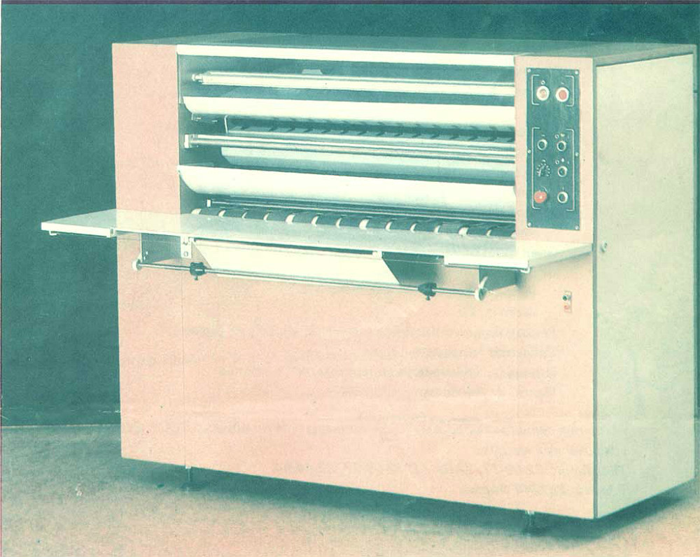
In the late 1960s, the USSR returned to the idea of \u200b\u200bcreating their copiers. At the Kazan Opto-Mechanical Plant began to collect the device "RAM" - rotary electronic circuit. It was released in two modifications - RAM-420 and RAM-620. The numbers indicated the width of the roll paper. The power of the electrical equipment of the first devices was very large. For example, RAM-620 consumed almost 8 kW of electricity. They weighed about a ton and worked on them two people.
A little later, similar devices began to make other plants - a white and the Grozny plant of printing machines under the brand "Era". It is noteworthy that in Grozny, small-informant devices were made under A3 and A4, which worked not only with rolling paper, but also with separate sheets.
"RAM" and "ERA", unlike the Frinkin apparatus, according to the principle of operation and the optical scheme, the "photocons" of the 1950-60s repeated in many ways. But when Western models were increasingly reliable, ergonomic and compact, the main advantage of Soviet was the low cost of consumables.
The first copying devices of the Soviet production were also fairly flawed. When stopping the paper movement, it almost immediately light up under the action of the heat flow from the infrared emitter. In the rooms where the technique was standing, had to install special system Fire extinguishing, and on the body of the apparatus, secure carbon dioxide fire extinguisher.
Among those who worked with Eoa and Rem devices, there was such a saying - "the operator who did not burn and did not extinguish the apparatus as a tanker who was not in battle." When admitting, the personnelists were seriously asked: "How many times wrong?"
Such techniques were made until the end of the 1980s. On this, the history of Soviet "copier" ended.
Vladimir Fridin:
In 1965, Chester Carlson visited our laboratory at the Crystallography Institute. The founder of the xerography became interested in my articles. We were photographed together with the help of an electropotor on the electrotherap. At the end of the 50s, Professor of Columbia University Hartmut Kalman with employees repeated my experiments on electrophotography on photoelectruts and found her an interesting use in space connection. He told about it at Colloquium in Munich, where we met in 1981. For these works, the American photographic society awarded me the Kozar medal, and German and Japanese were elected an honorary member.
In addition, in 2002, the International Committee for Photographic Science (International Committee For Imaging Science) awarded Vladimir Fridin Berg Prize for "Outstanding Contribution to the Development of Unusual (Filmless) photographic processes and international cooperation in this area."
Now the inventor is 83 years old.
Today, copying equipment is vital required tool For many organizations and companies that have not yet switched to a full internal electronic document flow. The Xerox brand has long become a nominal name for all copiers.
However, we could have a domestic "xerox". Attempts to create similar techniques were held in the mid-1950s, simultaneously with the developments of the Xerox itself. But the state then saw a threat to the uncontrolled distribution of data, therefore intentionally slowed down innovation.
It was believed that in the Soviet Union under the planned economy, the issue of operational copying of documents was not so acute as in countries with a free market. In numerous Soviet institutions, this problem was at first solved by photographic method and microphilm. The technical and design documentation had to be transferred manually on the tracing, multiply using aircraft. All this was long, difficult and uncomfortable.
"Xerox" Friedkin
Perhaps the most curious story is associated with the scientist Vladimir Fritony, whose invention anticipated the development of the industry for a decade.
Friedkin graduated in 1952 with a red diploma of the Fizfak of the Moscow State University. But for a long time I could not begin work in the specialty because of the problems "on the fifth point". The anti-Semitic campaign held at the time has reduced the benefits of a red diploma to zero.
Only a few months later, Vladimir Friedkin managed to get in research institutes of polygraphic engineering, although initially he wanted to become a nuclear physicist.
In Research Institute, Friedkin provided a completely empty office for work - there were only a table and a chair. To do something productive in such conditions was not easy.
Friedkin spent a lot of time in the reading room of Lenin's library, where a large meeting of documents, scientific works and books from around the world were kept. Once he read the article by American Chester Carlson's physics, which was devoted to photocopying. Then in the Soviet Union there was nothing like that. Fridin caught fire the idea of \u200b\u200bcreating a copy machine.
He appealed to the Electrical Engineering Department and asked him to allocate high voltage current generator. On his native Physifak MSU, he got sulfur crystals and the necessary photovoller. All experiments inventor spent in his small office. He managed to assemble the device called "Electroscopic Copy Device No. 1". The figure "1" in the title meant that others followed the first model.
Vladimir Friedkin:
I did not lose time. I went to Leninka, read magazines in physics, acquired some equipment. I came to mind the idea to implement a new photographic process in which the photoelector served as a photosensitive layer, and the manifestation was carried out using a triboelectric effect. The process was thinking also as a method for creating optical memory. The photoelector not only formed, but also remembered the image. The hidden image could be stored for quite a long time, and it could be shown after a long time after exposure. The layout was made quickly. I used polycrystalline sulfur, and then other photo conductors, such as zinc sulfide and cadmium. The manifestation was made by asphalt powder.
First, Friedkin tried to copy the page from the book, orders at the institute, then moved to photos. Once he made a copy from a picture of the Moscow street and showed it to the director of his research. He enthusiastically exclaimed: "You still understand what I invented?!".
Engineers of the Institute immediately was given an order to bring to mind that existed developments and collect a sample of a car that could make photocopies. Thus, Friedkin created the first copy machine in the USSR. Standing in autumn 1953.
Vladimir Friedkin:
Many years later, I learned that in the United States, in the company "Haloid", later renamed "Xerox", at the same time the first models began to appear. But their work was based on another principle.
The first Soviet copying apparatus was a box with a height of about one meter and a half-meter width. It was fixed by the current generator and two cylinders. The device turned out to be amazingly simple and understandable. Personally came to see the invention. He was so impressed with seen that he ordered to organize the mass production of new devices at the factory in Chisinau. And in Vilnius, special research engaged in electronization research was opened.
 Vladimir Fridin, who was then only 22 years old, became the Deputy Director of the Institute. He got a good cash premium. About the inventor even removed a television film dedicated to the achievements of Soviet science.
In 1955, the creator of the Soviet copying office moved to work at the Crystallography Institute. In the invention he took with him. Almost every day a colleague came to it to copy some scientific article from a foreign magazine. But in 1957 it all ended. "Somehow, the head of the specialty came to me - such departments were in every institute - and reported that the photocouples need to be written off," Friedkin told. The KGB believed that the machine could be used to distribute materials prohibited in the USSR.
The authorities then did not encourage the development of communication. For example, each radio is mandatoryly registered. State security bodies required to store prints from all printed machines if you need to install the author of the printout. There was a fight with Samizdat. The manuscripts of forbidden authors at night multiplied on typewriters. And then a fetal copying device unattended was found.
Soon the production of new devices was closed. The first of the collected models was dismantled. According to the legend, its most valuable part is the semiconductor plate - they retained and hung in the women's toilet of the institute as a mirror.
After years, the Soviet Union began to purchase copiers abroad. It was Xerox technique. One of these devices was brought to the Institute of Crystallography, which continued to work by Frigin. But it was already possible to use the technique only under the supervision of a special person who followed what copied by.

"RAM" and "ERA"
In the late 1960s, the USSR returned to the idea of \u200b\u200bcreating their copiers. At the Kazan Opto-Mechanical Plant began to collect the device "RAM" - rotary electronic circuit. It was released in two modifications - RAM-420 and RAM-620. The numbers indicated the width of the roll paper. The power of the electrical equipment of the first devices was very large. For example, RAM-620 consumed almost 8 kW of electricity. They weighed about a ton and worked on them two people.
A little later, similar devices began to make other plants - a white and the Grozny plant of printing machines under the brand "Era". It is noteworthy that in Grozny, small-informant devices were made under A3 and A4, which worked not only with rolling paper, but also with separate sheets.
"RAM" and "ERA", unlike the Frinkin apparatus, according to the principle of operation and the optical scheme, the "photocons" of the 1950-60s repeated in many ways. But when Western models were increasingly reliable, ergonomic and compact, the main advantage of Soviet was the low cost of consumables.
The first copying devices of the Soviet production were also fairly flawed. When stopping the paper movement, it almost immediately light up under the action of the heat flow from the infrared emitter. In the premises where the technique was standing, it was necessary to install a special system of fire extinguishing, and on the body of the device, the carbon dioxide fire extinguisher is fixed.
Among those who worked with Eoa and Rem devices, there was such a saying - "the operator who did not burn and did not extinguish the apparatus as a tanker who was not in battle." When admitting, the personnelists were seriously asked: "How many times wrong?"
Such techniques were made until the end of the 1980s. On this, the history of Soviet "copier" ended.
Vladimir Friedkin:
In 1965, Chester Carlson visited our laboratory at the Crystallography Institute. The founder of the xerography became interested in my articles. We were photographed together with the help of an electropotor on the electrotherap. At the end of the 50s, Professor of Columbia University Hartmut Kalman with employees repeated my experiments on electrophotography on photoelectruts and found her an interesting use in space connection. He told about it at Colloquium in Munich, where we met in 1981. For these works, the American photographic society awarded me the Kozar medal, and German and Japanese were elected an honorary member.
In addition, in 2002, the International Committee for Photographic Science (International Committee For Imaging Science) awarded Vladimir Fridin Berg Prize for "Outstanding Contribution to the Development of Unusual (Filmless) photographic processes and international cooperation in this area."
Now the inventor is 87 years old.